PDE implementation#
A two-way PDE estimation algorithm typically requires precise acquisition of phase changes across a span of frequencies by each participating device. The phases are derived from the captured I and Q samples in the receiver of a device for a tone transmitted by the peer device with a known raster.
The PDE implementation mainly consists of four steps: initialization and calibration, IQ data capture, phase processing, and distance estimation.
Initialization and calibration#
Before capturing the IQ samples, four important conditions must be met:
All transceiver impairments that can impact the phase capture information (DC offsets, IQ mismatch, filtering transfer function contributions, PLL phase excursions, and so on) must be minimized.
Theoretically, the IQ signal amplitude does not affect the phase calculations. However, signal saturation or fading can affect the accuracy of phase calculations. Ensure a good dynamic range for the captured IQ samples.
The measurement of phase differences implies that changes in phase are only produced by the distance between the test devices. The PLLs in both devices must remain frequency-coherent throughout the capture process.
Some algorithms require changing the tone frequencies with a specific time interval. The devices must synchronize their transmit and receive cycles accordingly.
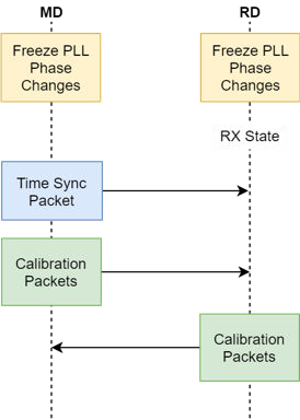
The initialization and calibration stages ensure that all of the above conditions are met before capturing the IQ samples.
Initialization and calibration sequence
Parent topic:PDE
IQ data capture#
Two-way PDE algorithms use multiple phase differences obtained at several frequencies. To achieve this, the MD and RD must generate Continuous-Wave (CW) tones and capture IQ samples in all the measurement frequencies.
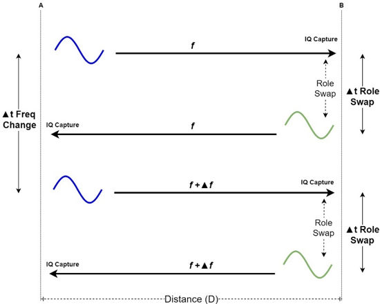
The base mechanism consists of device A, which generates a tone at frequency f. At the same time, the peer device B sets its radio to the RX mode at f and starts to capture IQ samples. After a fixed amount of time, devices A and B change roles. Now device B generates a tone in f and device A starts the RX and IQ capture at f. This is a tone exchange sequence.
After the tone exchange sequence ends, both devices return to their original roles, but the frequency is updated by Δf. For this new tone exchange, device A generates a tone at f + Δf. Device B also sets its radio to the RX mode at f + Δf and captures IQ samples. The tone exchange sequence is repeated for all frequency values that are defined for this measurement
Multiple frequency IQ samples capture sequence
Parent topic:PDE
Phase processing#
After the IQ samples are captured on each device, the phase difference is obtained using the following equation:
Equation 22. Phase from IQ samples

Each device holds the phase difference slope of the peer device against its own local oscillator. To obtain the phase combination result of the distance, the phase slope from the RD must be added to the phase slope from the MD.
Equation 23. Phase vector combination

This phase slope can now be used to perform distance estimation. As shown in Figure 21, depending on the frequencies used and the measured distance, phase wraps may occur.
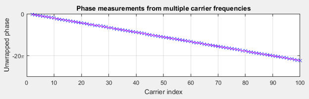
Figure 27 shows how the measured phase values change as a function of the carrier-frequency index. The data for this example is obtained using a wired setup, where the two devices are connected by a cable. A total of 99 carriers are used with the first carrier (index 2) corresponding to a frequency of 2400.5 MHz. The last carrier (with index 100) corresponds to a frequency of 2449.5 MHz. The frequency step size is 500 kHz.
Phase measurements (unwrapped) across multiple carrier frequencies

Parent topic:PDE
Distance estimation#
After the IQ samples are captured on each device, the phase difference is obtained using the following equation:
The phase vector obtained as a result of phase processing is the input for the distance-estimation algorithm. It can be used directly with Equation 16 for the slope method or as an IFFT input for the CDE method.
IFFT of phase vector
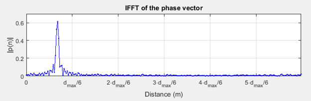
Figure 28 shows the IFFT magnitude response of the phase vector illustrated in Figure 27. The labels on the x-axis show the distance in meters. The final estimate is generally obtained from the peak location of the IFFT. The zero-meter compensation may be necessary to account for the delays within the radio front end.
Parent topic:PDE
Parent topic:RTP estimation fundamentals