How to manage Memory with MCUXpresso SDK CMake Projects#
This section explains how to configure your project’s memory management mechanishm including the linker file selection, linker’s sections, run functions or files from SRAM and external memory considerations.
Select your project’s linker file#
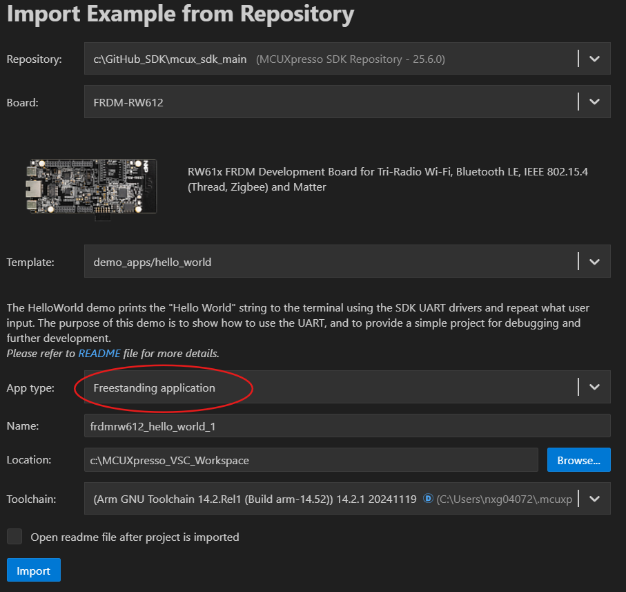
Import a project example as “Freestanding application”
Your imported project will appear in the left-side panel. In your project create a new folder called “sdk_patch” and within this folfer create a new file named “sdk_patch.cmake” as shown below:
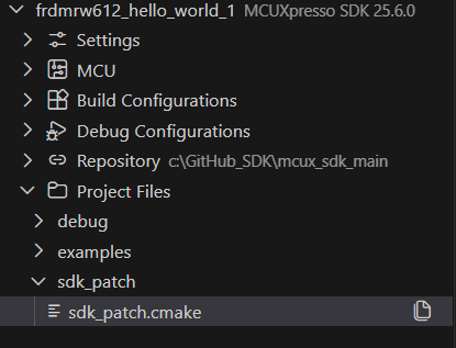
In your project’s CMakeList.txt, right before the last line, add an include for the sdk_patch.cmake:
include(
    ${PrjRootDirPath}/sdk_patch/sdk_patch.cmake
)
When you import a project example, a linker file will be automatically selected based on your device. However, if you need to change the linker file, you can do so by modifying the
sdk_patch.cmakefile. You need to remove the default linker file for the target by adding the following lines:mcux_remove_armgcc_linker_script( BASE_PATH ${SdkRootDirPath} TARGETS flash_debug flash_release LINKER ${device_root}/Wireless/RW/RW612/gcc/RW612_flash.ld )
Note: The linker scripts depends on your target device, you must locate it to correctly setup the sdk_patch.cmake file. The linker files are located at: /your_repo_path/mcuxsdk/devices/path_to_your_device/gcc
Select the linker file you want to use at the
sdk_patch.cmakefile. For this example, we are going to use the RW612_ram.ld instead of RW612_fash.ldmcux_add_armgcc_linker_script( TARGETS flash_debug flash_release LINKER ${device_root}/Wireless/RW/RW612/gcc/RW612_ram.ld )You can also use your custom linker file using the previous steps described by setting the linker path in the
sdk_patch.cmakefile. For example, if your custom linker is located in at/Project Files/linker/RW612_custom.ldyou need to set it up as:mcux_add_armgcc_linker_script( TARGETS flash_debug flash_release LINKER /../linker/RW612_custom.ld )
Using the linker File#
The linker file is used to define memory regions and tell the compiler how to organize code and data in memory. The linker script contains sections that map your code and data to specific memory areas (Flash, RAM, etc.).
Memory Regions in Linker Scripts#
The ARM gcc linker file defines memory regions using the MEMORY block. Here is a typical example:
MEMORY
{
  m_flash_config        (RX)  : ORIGIN = 0x08000000, LENGTH = 0x00001000
  m_interrupts          (RX)  : ORIGIN = 0x08001000, LENGTH = 0x00000280
  m_text                (RX)  : ORIGIN = 0x08001280, LENGTH = 0x001FED80
  m_data                (RW)  : ORIGIN = 0x20000000, LENGTH = 0x00130000
}
m_flash_config is a read and execute only region (RX) starting at address 0x08000000 with a length of 0x00001000 bytes (4 KB). This region typically stores flash configuration data.
m_interrupts is a read and execute only region (RX) starting at address 0x08001000 with a length of 0x00000280 bytes (640 bytes). This region contains the interrupt vector table.
m_text is a read and execute only region (RX) starting at address 0x08001280 with a length of 0x001FED80 bytes (~2 MB). This region stores the executable code.
m_data is a read and write region (RW) starting at address 0x20000000 with a length of 0x00130000 bytes (~1.25 MB). This region is used for initialized and uninitialized data in RAM.
Linker file sections#
The linker’s sections maps the application code and data into the memory regions defined in the MEMORY block. Each section specifies where code and data must be placed.
For example, the linker script uses the following section to place the interrupt vector table in the m_interrupts region:
SECTIONS
{
  .interrupts :
  {
    . = ALIGN(4);
    __VECTOR_TABLE = .;
    __Vectors = .;
    KEEP(*(.isr_vector))     /* Startup code */
    FILL(0x00)
    . = 0x280;
  } > m_interrupts

  /* More Sections*/
  ...
  ...
  ...
}
The section is defined as .interrupts and is placed in the m_interrupts memory region. This means that the source file that contains the interrupt table defined within the .isr_vector section will be placed at the beginning of the m_interrupts region.
. = ALIGN(4);aligns the current position to a 4-byte boundary.__VECTOR_TABLE = .;and__Vectors = .;create symbols that point to the start of the vector table, which can be referenced in C code.KEEP(*(.isr_vector))includes all.isr_vectorsections from all object files and prevents the linker from removing them during optimization.FILL(0x00)fills any gaps with 0x00 bytes.. = 0x280;sets the current position to 0x280 bytes (640 bytes), which is the size of the interrupt vector table, ensuring proper spacing for the next section.
In code, the vector table must be defined as follows to be placed in the correct location:
__attribute__ ((used, section(".isr_vector")))
void (* const g_pfnVectors[])(void) = {
    // Vector table entries
    &_vStackTop,                    // Initial Stack Pointer
    Reset_Handler,                  // Reset Handler
    NMI_Handler,                    // NMI Handler
    HardFault_Handler,              // Hard Fault Handler
    // ... other interrupt handlers
};
__attribute__((section(".isr_vector"))) tells the compiler to place this data in the .isr_vector section, which the linker script then places in the m_interrupts memory region at the correct address. used attribute ensures the compiler doesn’t optimize away this symbol even if it appears unused.
Mandatory Sections in the Linker File#
The mandatory sections in the linker file are the ones that must be present for the application to work correctly. This sections are defined to place code, read/write data or read-only data in specific memory regions.
.text Section#
.text :
  {
    . = ALIGN(4);
    *(.text)                 /* .text sections (code) */
    *(.text*)                /* .text* sections (code) */
    *(.rodata)               /* .rodata sections (constants, strings, etc.) */
    *(.rodata*)              /* .rodata* sections (constants, strings, etc.) */
    . = ALIGN(4);
  } > m_text
.textsection is used to place all executable code and read-only data (constants, strings) in the m_text memory region. This section is stored in non-volatile memory (flash).
.data Section#
  .data : AT(__DATA_ROM)
  {
    . = ALIGN(4);
    __DATA_RAM = .;
    __data_start__ = .;      /* create a global symbol at data start */
    *(CodeQuickAccess)       /* CodeQuickAccess sections */
    *(DataQuickAccess)       /* DataQuickAccess sections */
    *(.data)                 /* .data sections */
    *(.data*)                /* .data* sections */
    KEEP(*(.jcr*))
    . = ALIGN(4);
    __data_end__ = .;        /* define a global symbol at data end */
  } > m_data
.data section is used to place initialized data in RAM. The AT(__DATA_ROM) clause specifies that the section is loaded from flash memory at the address __DATA_ROM and then copied to RAM at runtime during the boot process. This allows initialized variables to persist across power cycles while being quickly accessible in RAM.
.bss Section#
  .bss :
  {
    /* This is used by the startup in order to initialize the .bss section */
    . = ALIGN(4);
    __START_BSS = .;
    __bss_start__ = .;
    *(.bss)
    *(.bss*)
    *(COMMON)
    . = ALIGN(4);
    __bss_end__ = .;
    __END_BSS = .;
  } > m_data
.bss section is used to place uninitialized data in RAM. The startup code uses the symbols __START_BSS and __END_BSS to initialize all uninitialized variables to zero during boot. Unlike the .data section, .bss data does not consume flash memory space since it only needs to be zeroed at runtime.
.heap#
 .heap :
  {
    . = ALIGN(8);
    __end__ = .;
    PROVIDE(end = .);
    __HeapBase = .;
    . += HEAP_SIZE;
    __HeapLimit = .;
    __heap_limit = .; /* Add for _sbrk */
  } > m_data
.heap section is used to allocate space for dynamic memory allocation (malloc/free). The section reserves HEAP_SIZE bytes in RAM for heap operations. Symbols like __HeapBase and __HeapLimit mark the start and end of the heap, allowing the memory allocator to manage dynamic memory within these boundaries. The __end__ symbol is used by the C library for memory management functions.
.stack Section#
 .stack :
  {
    . = ALIGN(8);
    . += STACK_SIZE;
  } > m_data

  /* Initializes stack on the end of block */
  __StackTop   = ORIGIN(m_data) + LENGTH(m_data);
  __StackLimit = __StackTop - STACK_SIZE;
  PROVIDE(__stack = __StackTop);
Note: These sections are tipically use into a linker script, however the user can define as much as sections it needs to place code and data into different memory regions.
Place code (functions) in RAM region#
Placing code in RAM can be useful for performance-critical sections or bootloader code that needs to execute before flash is initialized.
The default linker file in MCUXpresso defines a section called .ram_function which is used to place code in RAM. This is defined in the linker as:
.ram_function : AT(__DATA_END)
  {
    . = ALIGN(4);
    __ram_function_start__ = .;
    /* RAM function sections */
    . = ALIGN(4);
    __ram_function_end__ = .;
  } > m_data
This section places RAM functions in the m_data memory region. The AT(__DATA_END) clause specifies that the section is loaded from flash at the address __DATA_END and then copied to RAM at runtime. The symbols __ram_function_start__ and __ram_function_end__ mark the boundaries of the RAM function section, allowing the startup code to copy these functions from flash to RAM during initialization.
To place a function in RAM, use the __attribute__((section(".ram_function"))) directive previous to the function declaration and add the #define __STARTUP_INITIALIZE_RAMFUNCTION macro to your startup code to enable RAM function initialization.
__attribute__ ((section(".ram_function")))
int my_function(int arg0, int rag1){
  /* Do something*/
}
my_function will be placed in RAM instead of flash, allowing it to execute with lower latency. This is particularly useful for interrupt handlers or time-critical code paths where flash access latency could impact performance.