Channel Sounding steps description#
The CS defines a set of interlocked transfers between initiator and reflector. Within a CS procedure, CSStepCount shall be set to the current CS step number. The CS steps are constructed by a combination of modulated and unmodulated RF signals. The modulated sections convey synchronization information and extract the round-trip time information. The unmodulated sections are used to measure the phase rotation, which is proportional to the distance between the devices. The CS steps use the dedicated packet formats. There are 4 different modes for the CS steps. Each of these modes has different usage goals: measuring frequency offset between devices (mode 0), measuring round-trip times (mode 1), measuring phase rotations due to distance (mode 2), and measuring both round-trip times and phase rotations (mode 3). The CS steps require a precise timing synchronization between the initiator and reflector devices. Figure 5 shows a legend of the diagrams used in the following chapters to describe individual CS step modes.
Legend for CS step type packet description
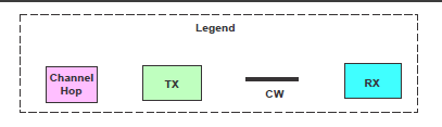
The colored time slots represent the following:
Channel Hop time slot
TX - transmitting time slot
CW - unmodulated continuous wave signal
RX - receiving time slot
The CS steps are separated by periods to perform a frequency hop. The structure is shown in Figure 6.
Channel hop period separates CS steps
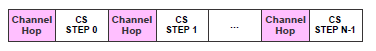
The time for the frequency hop is known as T_FCS. The initiator and reflector devices exchange the list of T_FCS values that each one can support during the capability procedure. The initiator selects a common T_FCS value during the configuration procedure. The permitted values for T_FCS are given by the BLE standard. Within a CS procedure, the same T_FCS value should be used for each channel hop. Both devices use the T_FCS period to perform internal calibrations in addition to the frequency change. The initiator or reflector may use this time period to allow the settling of the transmitted RF signal. It means that it reached a stable state when the subsequent CS step begins.
The set of variables used in the following chapters describes the CS step modes, as shown in Table 3.
Table 3. Channel Sounding step variables
Variable |
Description |
Time duration [us] |
|---|---|---|
T_FCS |
Time for frequency change spacing. The RF circuitry locks to the measurement channel (f_i). Devices can also use this time for additional internal calibrations, if necessary. The initiator may start to ramp up its output signal toward the end of this step |
15, 20, 30, 40, 50, 60, 80, 100, 120, 150 |
T_FM |
Time for frequency measurement |
80 |
T_SY |
Time for synchronization sequence (CS packet) |
26 for 2M PHY, 44 for 1M PHY |
T_IP1 |
Interlude period 1. The transition from TX to RX and the other way around when transmitting in mode 1 (Pk-Pk). |
10, 20, 30, 40, 50, 60, 80, 145 |
T_IP2 |
Interlude period 2. The transition from TX to RX and the other way around when transmitting in mode 2 (Tn-Tn). |
10, 20, 30, 40, 50, 60, 80, 145 |
T_GD |
Transition time between packet and tone |
10 |
T_RD |
Ramp-down time for transmission |
5 |
T_PM |
Single-antenna phase measurement period |
10, 20, 40 |
N_AP |
Number of antenna paths |
1, 2, 3, 4 |
T_SW |
Antenna switching period |
1, 2, 4, 10 |
N_AP*T_PM |
Phase measurement period. This measurement must be performed for each antenna path. N_AP is the total number of antenna paths. Transmitted signals are expected to be stable during this period. When multiple antenna paths are used, an equivalent number of T_PM periods is used. Each T_PM reserves the first 2 us for antenna switching (T_SW). |
- |
CS step mode 0#
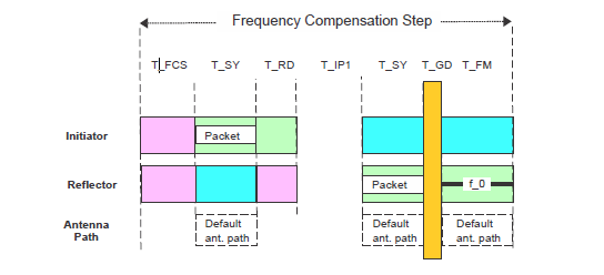
TCS step mode 0 is used to measure the frequency offset between the initiator and the reflector at a given frequency. The step mode 0 is a basic step supported by all the devices with CS feature. Figure 7 shows the exchange defined for CS step mode 0.
CS step Mode 0 packet exchange

The frequency hop is created before each CS step. The initiator starts by transmitting the CS SYNC packet (T_SY). The duration of the packet is shown in Table 3. The initiator performs a measurement of the frequency offset from the transmitted RF signals from the reflector during CS step mode 0. The initiator shall use this information to compensate all further transmissions within the subsequent CS steps in a CS event. This is used for synchronization purposes.
After the transmission from the initiator completes, a defined ramp-down window of 5 us (T_RD) is allowed for the initiator to remove the transmitted energy from the RF channel. After T_RD, the output power shall be lower by 40 dB than the output power used during the transmission of the CS SYNC packet (measured at the initiator’s antenna).
T_IP1 represents the idle time between the transmission from the initiator and the transmission from the reflector. Devices may use this time for internal calibrations, if needed. The reflector can use this time to ramp up its transmitted signal (if necessary) in advance of the transmission of the CS SYNC packet (T_SY) with the unmodulated carrier after synchronization. A transition time from packet to tone (T_GD) is needed. Then the reflector device makes the frequency-measurement period. The duration of this period (T_FM) for CS mode 0 shall be 80 us. The frequency measurement period ends the CS step mode 0 procedure.
It is important to mention 2 packet formats for channel sounding. Channel sounding uses a specific modulated bit sequence known as CS SYNC. The CS SYNC packet format is similar to a packet format for uncoded PHY, but it has no CRC. The CS SYNC packet has a specific format shown in Figure 8.
CS SYNC packet format
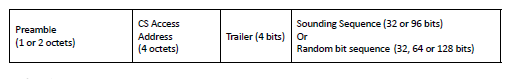
The preamble is 1 octet when transmitting or receiving on the LE 1M PHY and 2 octets when transmitting or receiving on the LE 2M PHY. The CS access address is 4 octets. The trailer is 4 bits. The sounding sequence or random bit sequence are optional fields. If present, the sounding sequence shall be 32 or 96 bits long. If the random bit sequence is present, it shall be 32, 64, or 128 bits long.
The variable length of the optional sounding sequence and random bit sequence allows an implementation to optimize the total packet length vs the correlation accuracy of the field. CS packets with no sounding or random bit sequence take 44 us to transmit when sent by LE 1M PHY and 26 us to transmit when sent by LE 2M PHY. CS packets that include a sounding or random bit sequence take proportionally longer to transmit, based on the length of the field and the PHY selection.
Parent topic:The channel sounding steps description
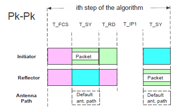
CS step mode 1#
CS mode 1 is used to measure the round-trip time between the initiator and the reflector. Devices supporting the CS feature shall implement the CS step mode 1. This mode uses the theoretical background described in RTT estimation fundamentals. The packet structure in Figure 9 is defined for CS step mode 1. Before each CS step, a frequency hop is created
CS step mode 1 packet exchange

The initiator starts by transmitting the CS SYNC packet. The duration of the CS SYNC packet is marked as T_SY. In this case, CS step mode 1 may include a payload as part of the CS SYNC packet. After the transmission from the initiator completes, a defined ramp down window of 5 us is allowed. It helps the initiator to remove the transmitted energy from the RF channel. After the ramp down, the output power shall be lower by 40 dB than the output power used during the transmission of the packet, measured at the initiator’s antenna.
T_IP1 represents the idle time between the transmission from the initiator and the transmission from the reflector. Devices may use this time for internal calibrations, if needed. The reflector can use this time to ramp up its transmitted signal (if necessary) in advance of the transmission of the CS SYNC packet. The duration of T_IP1 is shown in Table 3. After T_IP1, the reflector device transmits its CS SYNC packet. The CS step mode 1 may have a payload as part of the CS SYNC packet. The reflector may transmit its CS SYNC packet even if it does not receive a previous CS SYNC packet from the initiator or if the CS SYNC packet was received with bit errors.
Parent topic:The channel sounding steps description
CS step mode 2#
CS mode 2 is used to measure the phase rotations of the RF signal between the initiator and the reflector. The theoretical description of this mode is in RTP estimation fundamentals. The devices supporting this feature should fully support CS step mode 2. The structure of CS step mode 2 is shown in Figure 10.
CS step mode 2 tone exchange
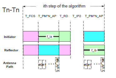
Before each CS step, a frequency hop is created. The duration of the frequency hop is marked as T_FC. The initiator starts the transmission with an Unmodulated Carrier (UC) RF signal. The duration of the unmodulated carrier RF signal should be T_PM*N_AP, where T_PM is the phase-measurement period and N_AP is the number of antenna paths. Each individual T_PM reserves the first configurable time (1, 2, 4, 10 us) for antenna switching. The available values of T_PM are given by the standard and shown in Table 4.
Table 4. Permitted values for T_PM
T_PM Index |
T_PM |
Comment |
|---|---|---|
1 |
10 us |
Optional |
2 |
20 us |
Mandatory if any shorter T_PM extent is supported, else optional |
3 |
40 us |
Mandatory |
For added security, each N_AP set of T_PM length transmissions shall be followed by a single tone-extension slot of the same T_PM extent. This tone-extension slot may or may not carry a transmission. The presence of the added security is controlled by random bit generation.
After the transmission from the initiator completes, a defined ramp-down window of 5 us is allowed for the initiator to remove the transmitted energy from the RF channel. The same rule is applied here. The output power shall be lower by 40 dB than the output power used during the transmission of the UC RF signal. The signal level is measured at the initiator’s antenna. T_IP2 represents the idle time between the transmission including the tone extension slot from the initiator and the transmission from the reflector. Devices may use this time for internal calibrations (if needed). The reflector can use this time to ramp up its transmitted signal (if necessary) in advance of the transmission of the UC. The permitted values for T_IP2 are shown in Table 5. The T_IP1 value can be different from T_IP2.
Table 5. Permitted values for T_IP2
T_IP2 Index |
T_IP2 |
Description |
|---|---|---|
1 |
10 us |
Optional |
2 |
20 us |
Optional |
3 |
30 us |
Optional |
4 |
40 us |
Mandatory if any shorter T_PM extent is supported, else optional |
5 |
50 us |
Optional |
6 |
60 us |
Optional |
7 |
80 us |
Mandatory if any shorter T_PM extent is supported, else optional |
8 |
145 us |
Mandatory |
After T_IP2, the reflector device transmits its (UC) RF signal. The duration of the unmodulated carrier RF signal should be T_PM*N_AP, where T_PM is the phase-measurement period and N_AP is the number of antenna paths. Each individual T_PM reserves the first 2 us for antenna switching. The N_AP parameter is common to the entire CS procedure and shall range from 1 to 4. An added extension transmission slot shall immediately follow the last valid N_AP transmission, as it was similarly present in the initiator-to-reflector direction. If a transmission is present, it shall be identical to that of the last T_PM slot and it shall use the same antenna element used in that slot. If a transmission is not present in the tone-extension slot, then that T_PM period shall still be present but not carry a transmission. The presence of the added security is controlled by the random bit generation.
Parent topic:The channel sounding steps description
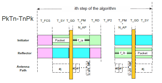
CS step mode 3#
CS step mode 3 is used to measure the phase rotations of the RF signal and the round-trip time between the initiator and the reflector. It uses a combination of the previous modes. All the devices supporting the CS feature may optionally implement also step mode 3. Figure 11 is defined for CS step mode 3.
CS step mode 3 packet exchange

A frequency hop is created before each CS step. The channel hop duration is marked as T_FCS. In the reflector to initiator direction, the duration is given by the CS SYNC synchronization packet (T_SY), transition time between the packet mode to tone (T_GD), and the unmodulated carrier RF signal T_PM*N_AP. T_PM is the phase-measurement period and N_AP is the number of antenna paths. Each individual T_PM reserves the first configurable time (1, 2, 4, 10 us) for the antenna switching (T_SW).
If a tone-extension slot is present, then the tone duration is (T_SW+T_PM)x(N_AP+1). If the tone-extension slot is not present, then the tone duration is (T_SW+T_PM) x N_AP. To compensate for the missing tone slot a “no tone” slot is added after the synchronization.
The initiator starts a transmission with the Unmodulated Carrier (UC) RF signal. The duration of the unmodulated carrier RF signal should be T_PM*(N_AP + 1) and it should also depend on the physical layer used. CS step mode 3 may use a payload as part of the synchronization.
For added security, each N_AP set of T_PM length transmissions shall be followed by a single tone-extension slot of the same T_PM extent. This tone-extension slot may or may not carry a transmission. If a transmission is present, it shall be identical to that of the last T_PM slot and it shall use the same antenna element used in that slot. If a transmission is not present in the tone-extension slot, then that T_PM period shall still be present, but it shall not carry a transmission. The presence of a physical transmission in the extension transmission slot is seeded by the random bit generation.
After the transmission from the initiator is completed, a defined ramp down window of 5 us (T_RD) is allowed for the initiator to remove the transmitted energy from the RF channel. After T_RD, the output power should be lower by 40 dB than the output power during the transmission of the synchronization. This is measured at the initiator’s antenna.
T_IP2 represents the idle time between the transmission from the initiator and the reflector. Devices may use this time for internal calibrations (if needed). The reflector can use this time to ramp up its transmitted signal before the transmission. The duration of T_IP2 is defined the same way as the CS step mode 2 in Table 5.
After T_IP2, the reflector device transmits a CS synchronization using the unmodulated carrier. The duration of the unmodulated carrier shall be either T_PMxN_AP or T_PMx(N_AP + 1). This depends on whether a transmission is selected for the tone extension slot. If a transmission is present, it should be identical to that of the last T_PM slot and it shall use the same antenna element as in that slot. If a transmission is not present in the tone-extension slot, then the T_PM period should not be present. The presence of a physical transmission in the extension is controlled by the random bit generation.
The reflector device may then transmit its CS synchronization even if it does not receive a CS synchronization from the initiator or if the synchronization was received with bit errors.
Parent topic:The channel sounding steps description
Channel Sounding mode sequencing#
The CS mode sequencing describes specific time slots of the whole flow. The CS event will always start with one or more mode 0 steps, which is represented by blue rectangles in FFigure 12. A series of subsequent non-mode 0 steps shall follow in the same event. Any CS procedure shall only use at most two non-mode 0 modes. One of these two is known as the main mode and the other is known as the submode. An example of this sequencing is shown in Figure 12. Many other CS mode sequencing examples can be generated.
Channel Sounding mode sequencing
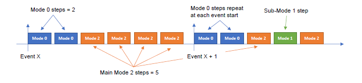
The submode insertion sequences the occurrence of the main mode steps and the submode steps and uses the following parameters:
Main_Mode_Min_Steps – the minimum main-mode steps that shall occur before a single submode step.
Main_Mode_Max_Steps – the maximum main-mode steps that shall occur before a single submode step.
The number of main-mode steps that occur before a submode step shall be between Main_Mode_Min_Steps and Main_Mode_Max_Steps, inclusive. The exact number of main-mode steps that occur before a submode step insertion is randomized for each sequence. The randomized function is defined by the BLE standard.
Parent topic:The channel sounding steps description
Parent topic:The channel sounding standard description