System Manager Configuration Tool#
The System Manager Configuration tool allows you to configure a project with the System Manager (SM) application on i.MX 9 series processors.
System Manager is a low-level system function that runs on a System Control Processor (SCP) and is intended to support isolation and management of power domains, clocks, resets, sensors, pins on complex application processors. It typically executes on Cortex-M processor architectures and delivers a comprehensive abstraction layer for the underlying hardware functionality. The primary purpose of SM is to allow isolation between software running on different cores in the SoC. This is accomplished by maintaining exclusive access to critical resources—such as power, clocks, reset, and PMIC—while providing an RPC interface to those clients (agents). This allows SM to provide access control, arbitration, and aggregation policies for shared critical resources.
System Manager tool#
SM configuration#
Configuration of SM determines how the device (SoC) will be divided between Logical Machines (LM) and specifies the ownership of peripherals and memory. This ownership is used to determine API access rights to resources (clocks, pins, and so on) and CPU access rights to peripherals and memory (for example, RDC configuration). SM determines which LM will boot at POR and what RPC API functions the agents on those LM can call.
NXP provides the SM along with example board configurations. The configuration specifies the associated device and board (in most of the cases, a new configuration must be created for a customer product).
SM project settings and files description#
The SM tool loads and processes data from a specified location of a SM Firmware project (for example, nxp-imx/imx-sm) by using the Project Settings wizard available in the System Manager toolbar.

System Manager toolbar - Project Settings wizard and Import/Export options#
Create an empty configuration based on the available board and device configuration (this option is suitable for developers of new or unsupported boards) or import an existing SM project configuration from CFG (for example, mx95evk.cfg from an SM FW repository) or a JSON file. Problems that occur during the configuration import are displayed in the report dialog that can be exported. In case of any issues, review the report and adjust the configuration accordingly.
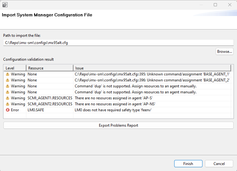
Problems reporting during import#
The SM tool generates SM configuration source files that can be exported to the project location. The tool generates source files of the following types:
Doxygen DOX file (
config.dox)MAK file (
config.mak)Configuration header files (for example,
config_scmi.h,config_trdc_h)
Apart from that, the SM tool can convert CFG files to the JSON format in the form of Resource Database JSON files and a user configuration JSON file. These files can be exported by using the export dialog.
atomic_resources.jsoncontains available device and board specific atomic resources that can be configured by SM FW for a selected chip (pins, clocks, power domains, security peripheral regions, controls, faults).macro_resources.jsoncontains predefined macro resources defined by SM FW. Macro resource defines a group of atomic resources that describe a bigger logical cluster of HW resources. For example, Macro resource LPUART1 can specify a power domain, clock, memory block checker. A peripheral instance that can be assigned to any of the Resource Owners specified by HW and SM FW - Domain (DOM), Logical Machine (LM), or Agent.chip_data.jsoncontains chip-specific information needed for SM FW configuration, such as security peripheral description.error_log.jsoncontains configuration problems that occur during input files parsing or output generation.user_configuration.jsoncontains the current SM project configuration state.
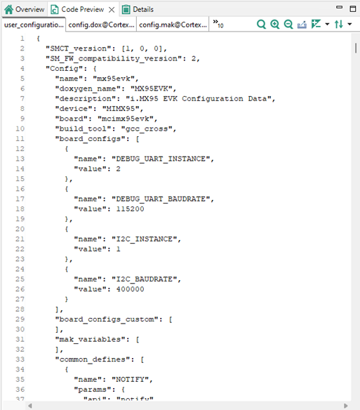
Generated user_configuration.json file#
User interface overview#
The SM tool consists of several views available to configure the SM project and to generate expected SM FW source files.
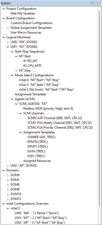
System view#
The System view shows an overview of configurable elements and their important details of the System Manager project in the form of a project navigation tree. The System view allows you to configure Resource Owner specific settings, such as RPC protocol, Transport, Mailbox, and Assignment Templates (definition of a group of parameters that will be assigned to a Resource Owner). These are the main categories that can be configured.
Project Configuration – SM project configuration name and description, compiler Mak file configuration
Board Configuration – Board specific settings, SM debug options, Global Assignment Templates definition, creation of custom User Macro Resources
Logical Machines – LM specific settings (for example, RPC), Mode Select Configurations from LM’s perspective, Start-Stop Sequences configuration, Assignment Templates definition
Agents – SCMI Agent specific settings (for example, Mailbox), Assignment Templates definition
RPC Channels – Channel settings (for example, transport)
Domains – DOM specific settings, Assignment Templates definition
mSel Configurations Overview - Mode Select Configurations from mSel’s perspective
To configure a generic System Manager project setting, for example, Project Mak file or debug features, use the System view tree to select the desired node. Every selection of the tree node shows available configuration settings in the configuration Details view. To expand/collapse all child nodes of the active selection, use the Expand/Collapse buttons on the System view’s header.
System View#
Details view configuration#
The Details view displays and allows changing SM element settings information.
The information is dynamically updated to reflect modifications in the System, Boot, or Resources views.
In the Details view, the following actions can be performed:
To display the element information, point the mouse cursor at the SM element.
Inspect the SM element in the System, Boot, or Resources views.
Modify the SM element settings by left-clicking the element value. There are the following types of settings:
Textbox – Left-click and type the value.
Dropdown – Left-click and select one of the offered values.
Checkbox – Let-click to set (enable) the element.
Button - Left-click to trigger an action or move to a specific configuration section.
Information – This setting type cannot be modified and is used to inform about a specified value.
Add an element to the table by left-clicking the plus button.
Remove an element from the table by left-clicking the cross button.
Navigate to the parent setting via the Navigation bar on the top of the Details view.

Configuration details view of the selected agent#
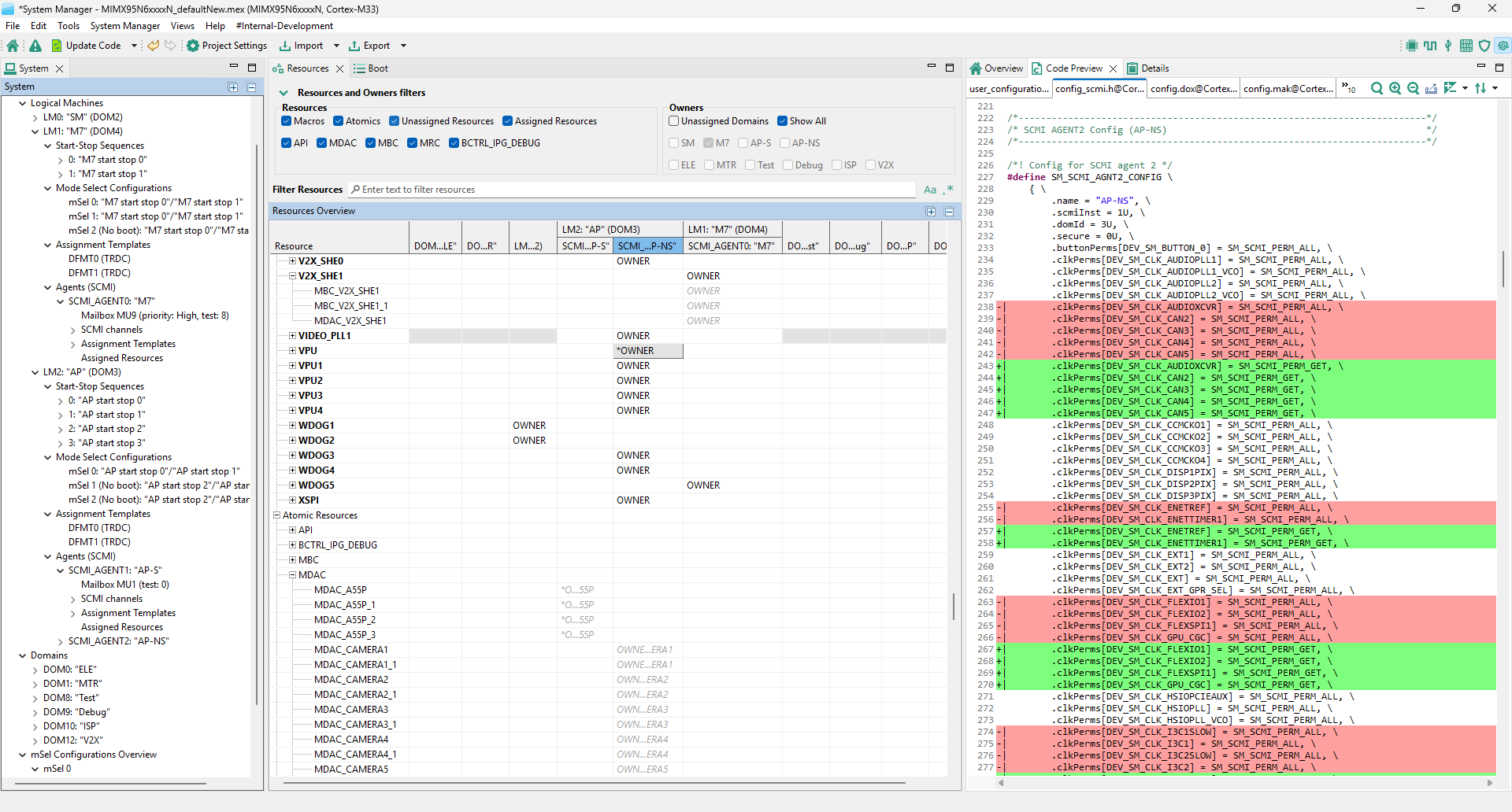
Resources view#
The Resources view shows an overview of resources assigned to Resource Owners and is used as a way of navigation to show the details of the selected resource assignment. The assignment is usually set by the Assignment Template that represents assigned parameters to the resource. After an Assignment Template is set to a resource, it is possible to configure additional available parameters related to the resource in the Configuration Details view.
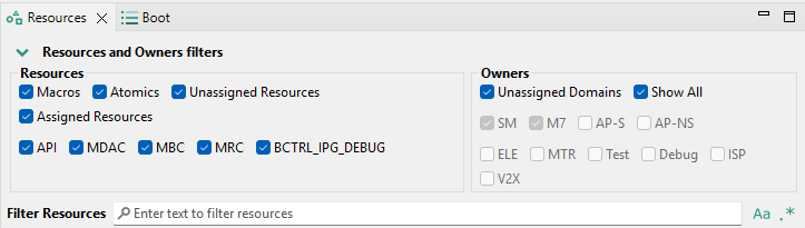
The top of the Resources view contains various filters that can be used to specify the overview intention. Filter Resource Owners using specified filters and Resources using the search bar or specified filters.
Access control takes two forms, API access via an agent’s MU and RDC access for a DID. Each LM is a unique DID and can have multiple agents, which all have the same DID.
To assign a resource to a Resource Owner (LM, SCMI_AGENT, DOM) use the Resources view.
Assign and configure Resource parameters - Select the cell with the corresponding Resource (row) and the Resource Owner (column) in the Resources view. Click the Assign button in the configuration Details view.
Assign a resource with pre-configured Assignment Templates - Using the System and Details views configure the Assignment Templates for the desired Resource owner - Set the name (identifier) and Resource parameters to be configured (parameters that do not relate to the assigning Resource are ignored).
Assign a resource with pre-configured mandatory (required) Assignment Templates DFMT0 and DFMT1 - Resources that configure Atomic Resource of the type MDAC require mandatory Assignment Templates DFMT0 for CPU and DFMT1 for non-CPU bus-masters to apply. The required templates are assigned automatically.
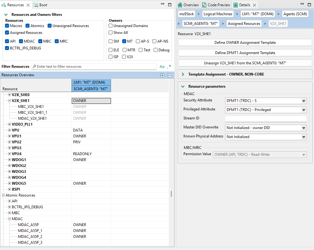
Selection of Resource Assignment in the Resources view#
Create a new memory sector - Select the corresponding Resource (row) with the <MEM> suffix and the Resource Owner (column) in the Resources View. Double-click the desired cell and select Create a new memory sector. Then configure the memory sector parameters (Start Address, Size or End Address, and Permissions) in the Details View.
Assign an existing memory sector to a Resource owner - Expand the Resource (row) with the <MEM> suffix node, select the memory sector, and double-click the cell to select the template or assign the memory sector.

Example of Memory resource assignment - M7MIX<0x20380000-0x2047ffff> to ELE Domain#
To modify parameters of the resource assignment, select the resource and use the Details view:
Use the Template Assignment section to select and see configured parameters assigned by the Assignment Template. Modify the Assignment Template parameters by selecting the checkbox to enable editing.
Note: Updating the selected Assignment Template affects all Resources that are assigned to this template.
To configure additional parameters to the selected Assignment template, select the settings below the Assignment Template selection.
Note: The parameters that are not available are not related to the Resource. The parameters that are grayed are configured by the Assignment Template and cannot be overwritten. To change the grayed setting value, create a new, choose another, or update the selected Assignment Template.
To remove the Resource assignment, select the cell with the corresponding Resource (row) and the Resource Owner (column) in the Resources view. Then click the Unassign button in the configuration Details view.
To find a desired Resource or to adjust the overview table, use the Filter or the search bar. To achieve that, combine the selection of Resources and Owners filters with the search bar filtering. The search bar supports case-sensitive and regular expression search. It can be enabled by clicking the buttons on the right side of the search bar.
Note: Macro Resources can be expanded in the Resources view to see all Atomic Resources that are included in the resource assignment.
Filtering a resource#
Boot view#
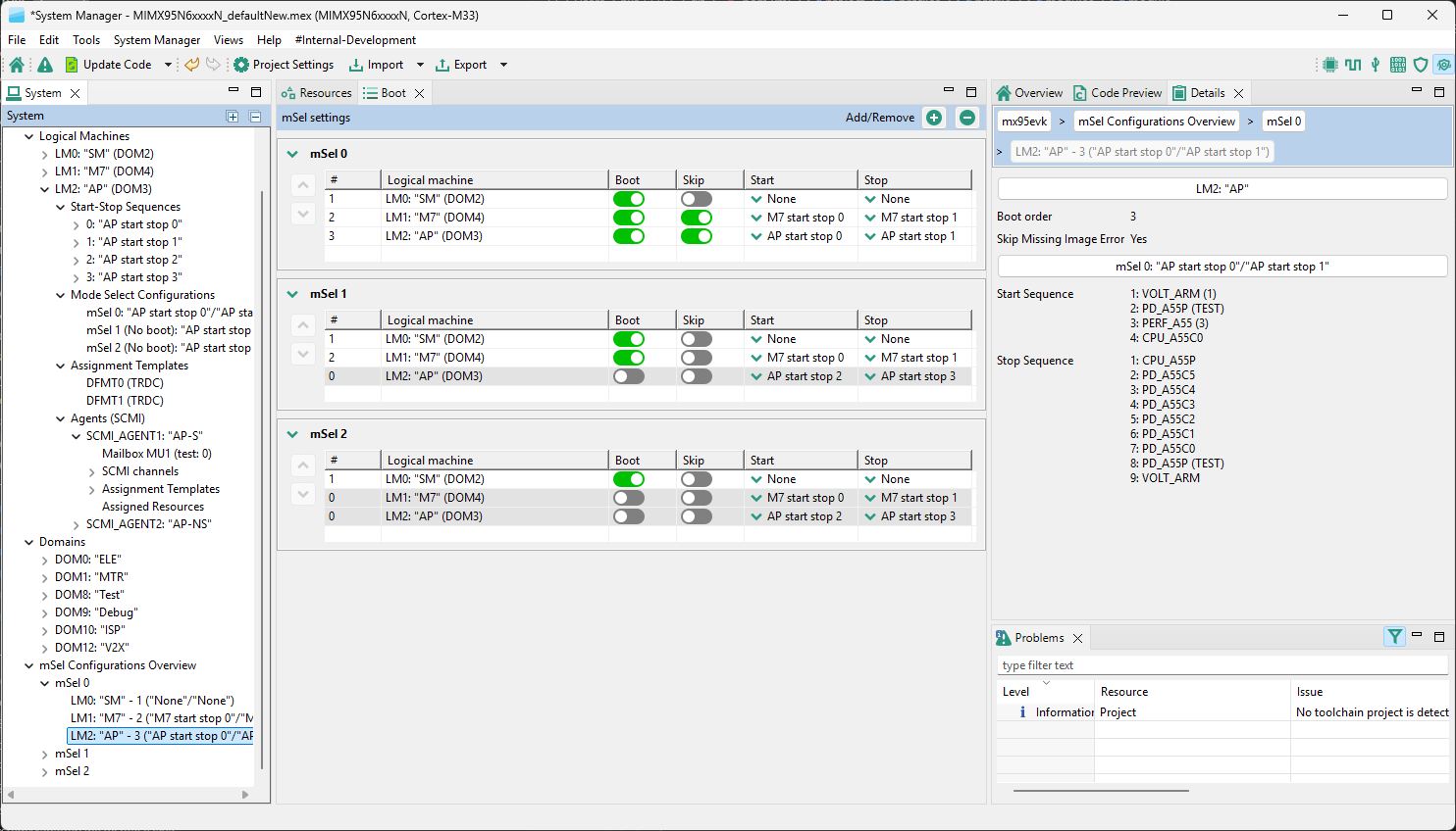
The Boot view shows an overview of an independent lifecycle execution of LMs and configuration of boot Mode Select (mSel) options. The following options can be configured:
The new mSel mode can be added or removed to the System Manager configuration by clicking Add/Remove buttons in the header of the Boot view.
In the Boot view, the mSel table lists logical machines in the boot order. If a machine’s boot is disabled, it stays in its position but its index changes to 0 and the remaining machines are renumbered accordingly. To reorder items, select one and click the Up or Down button.
In the Details view of the selected Logical Machine, the Relative time to the time the SM starts to boot Logical machines can be configured.
In the Boot view, each LM can have multiple boot configurations with different start and stop sequences. It can be determined if the LM is booted when the SM boots in every mSel section.
Configuration of the “bootskip” flag skips an error due to no image in the boot container.
Selection of the configuration of the Start and Stop commands that are to be executed when an LM is booted or shutdown (sequences)
To add, remove or modify a Start-Stop Sequence, select the LM to be affected from the desired mSel section and using the Details view
Use plus/minus buttons to add or remove a Start-Stop Sequence
Double-click the Start-Stop Sequence to open its configuration details to be modified
Modify the index (identifier) and user name of the Start-Stop Sequence
Use plus/minus buttons to add or remove a Resources Commands to be called in the sequence
Double-click the Resource Command to open its configuration details to be modified (selection of Resource Command, optional arguments, and unit test flag)
Boot view#
Code generation#
If the settings are correct and no error is reported, the code generation engine instantly regenerates the source code. The resulting code is visible in the Code preview view of the System Manager tool.
Code preview automatically highlights differences between the current and immediately preceding iteration of the code. It is possible to choose between two modes of highlighting by clicking the Set viewing style for source differences. Highlighting can be disabled from the same dropdown menu. Such features as Copy, Search, Zoom-in, Zoom-out, and Export source are available in the Code Preview view. The search can also be invoked by CTRL+F or from the context menu.
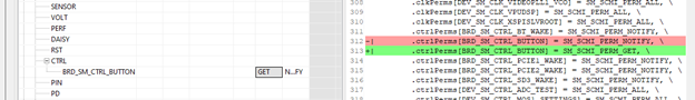
Highlighted change of the code#
Use cases workflow#
This section lists steps how to configure specific System Manager parts or functions. The typical use case of the tool starts with importing of the existing configuration. Creating an empty configuration is suited for the development process of the completely new board or processor that is not yet supported by the official release of the System Manager Firmware.
After selecting a supported processor, import an existing configuration of the SM project in CFG format using the Project settings wizard.
To configure a generic System Manager project setting, for example Project Mak file or debug features, use System view’s tree to select the desired element. Every selection of the tree element shows you available configuration settings in the Configuration Details view.
To configure a setting related to booting of the Logical Machines, use the Boot view
To add or remove the mSel configuration, use the plus/minus buttons in the left pane of the Boot view
In the desired mSel section configure parameters for each Logical Machine:
Select LM and use Details view to configure Boot related parameters and add or modify Start/Stop sequences of Resource Command calls.
By enabling the Boot parameter, the index of the Logical Machine corresponds with the actual boot order (index 0 means that LM will not boot)
Enable the optional “Skip” parameter to skip the booting error message and select the Start and Stop sequences.
Use the Resources view to assign a Resource to a Resource Owner (every Resource Owner is related to a specific TRDC domain).
To find a desired Resource or to adjust the overview table use the Filter or Search bar
To add a new assignment, double-click on the desired Macro or the Atomic resource (row) related to the Owner (column) and assign a resource or a template.
To remove an existing assignment, select the assignment and click the Unassign button in the Details view.
To modify an assignment, click the resource and use Details view.
To adjust the overview of the Resource assignments, use a filter or search bar that is part of the Resources view