Peripherals Tool#
This chapter provides general information about the Peripherals Tool.
Features#
The Peripherals tool features:
Configuration of initialization for SDK drivers
User-friendly user interface allowing to inspect and modify settings
Smart configuration component selection along the SDK drivers used in toolchain project
Instant validation of basic constraints and problems in configuration
Generation of initialization source code using SDK function calls
Multiple functional-group support for initialization alternatives
Configuration problems are shown in the Problems view and marked with decorators in other views
Integration in Tools framework along with other tools
Middleware configuration support (USB, FREEMaster, LwIP)
The settings can be automatically migrated to a different SDK component version
Support of code snippets
Basic Terms and definitions#
Term |
Definition |
|---|---|
Functional group |
Represents a group of peripherals that are initialized as a group. The tool generates a C function for each functional group that contains the initialization code for the peripheral instances in this group. Only one functional group can be selected as default initialization, the others are treated as alternatives that are not initialized by default. |
Peripheral instance |
Occurrence of a peripheral (device) of specific type. For example, UART peripheral has three instances on the selected processor, so there are UART0, UART1, and UART2 devices. |
Configuration component |
Provides user interface for configuring SDK software component (for example, peripheral driver) and generates code for its initialization. |
Component instance |
Configuration component can have multiple instances with different settings. (for example, for each peripheral instance like UART0, UART1). |
Component mode |
Specific use case of the component instance (for example, TRANSFER mode of DSPI, or interrupt-based mode of communication). |
Workflow#
The following steps briefly describe the basic workflow in the Peripherals tool.
In the Peripherals view, select the peripheral instance you would like to configure (use the checkbox).
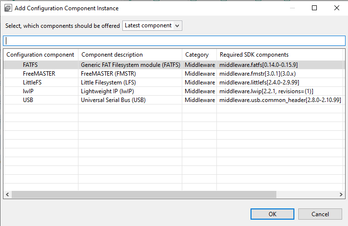
In case more components are available for use by the peripheral, the Select component dialog appears. The dialog displays the list of suitable configuration components for the selected peripheral matching the SDK driver for the selected processor.
Select the component that you want to use and click OK.
In the settings editor that automatically opens, select the Component mode that you would like to use and configure individual settings.
Note: The selection of the component mode may impact appearance of some settings. Therefore, the selection of the mode must be always the first step.
Open the Code Preview and see the output source code.
Note: The source code preview is automatically generated after each change if no error is reported.
You can use the Update Code button from the toolbar. Alternatively, you can export the source code by selecting File > Export… from the Menu bar.
Note: To export the source code, you can also click the Export button in the Code Preview view.
Settings can be saved in a MEX format (used for all settings of all tools) by selecting File > Save from the Menu bar.
User interface overview#
Peripheral view#
Components view#
Common toolbar (Peripherals)#
In addition to general items available to all tools, the Toolbar of the Peripherals tool contains two additional items:
Item |
Description |
|---|---|
Global settings |
Open a tab aggregating global settings of all configuration sets. |
Initialization order |
Open a dialog for customization of peripheral initialization order. |
Note: For details on other items, refer to the Toolbar chapter.
Initialization order dialog#
In the Initialization order dialog, you can customize the initialization order of peripherals within selected functional groups.
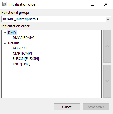
Initialization order dialog#
Select the functional group you want to modify using the Functional group dropdown list.
In the Initialization order list, use the up and down arrows to adjust the sequence of initialization.
Click Save order to save your settings, or Cancel to close the dialog without changes.
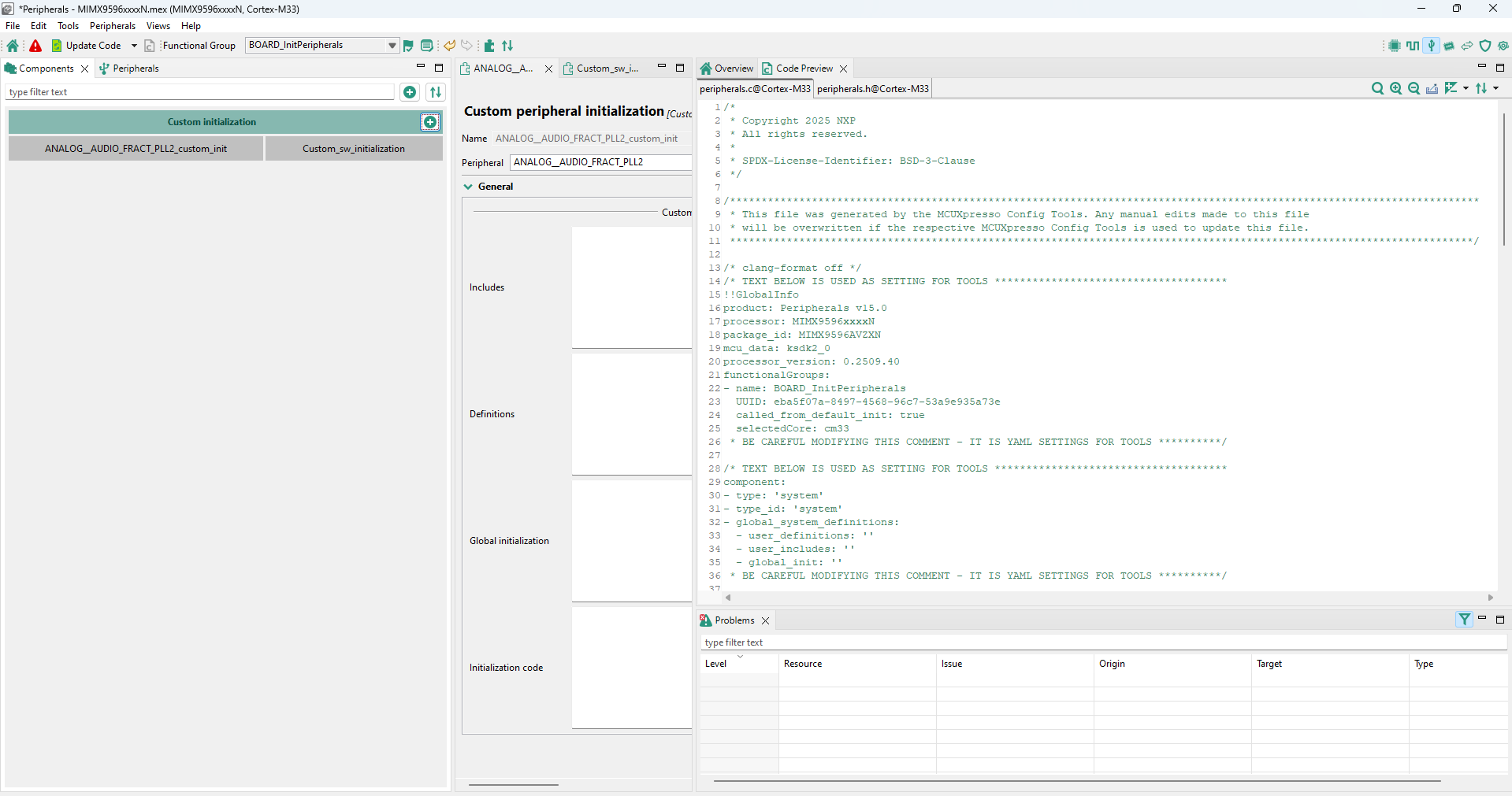
Components view#
The components view shows a list of configuration components, sorted by category into groups such as Middleware, Peripheral drivers and others.
The view highlights configuration components based on their status.
Status |
Color highlighting |
|---|---|
Enabled |
Light gray. |
Enabled/with warning |
Light gray with the alert symbol. |
Enabled/with error |
Red with the error symbol. |
Disabled |
Dark gray. |
Components view#
In the Components view, you can perform several actions.
Option |
Description |
|---|---|
Display configuration-component information |
Point the mouse cursor at the configuration component to display general configuration-component information. |
Open the Settings Editor of the configuration component |
Left-click the configuration component to open its Settings Editor. |
Add new configuration components |
Left-click the + button and select from the list to add a component. In the Select component dialog, you can filter the list to show only toolchain-project-relevant, or latest version components. You can also click the + buttons next to Middleware/Peripheral drivers/Other categories to add new components in them directly. |
Filter configuration components by name |
Type a text string to filter configuration component names in the search bar. |
Add component dialog#
Right-click the the configuration component to open a shortcut menu. Several options are available in the shortcut menu.
Option |
Description |
|---|---|
Open |
Open the configuration component in the Settings Editor. |
Open in another view |
Duplicates the configuration component in the Settings Editor. |
Enable/Disable |
Enable/Disable the configuration component. |
Edit comment |
Create/Edit custom notes for the configuration component. |
Lock/Unlock editing of component instance |
Lock/Unlock the editing of the component instance. |
Save to use case library |
Create a template from the configuration component. |
Documentation |
Display the documentation of the configuration component, if available. |
Remove |
Remove the component from configuration.Note: If the component has any global settings, a dialog appears prompting you to confirm the removal. If the component doesn’t have any global settings, the component is deleted after removing the last instance. |
Migrate |
Migrate the component to a different component type or to a component with a newer driver version. |
Move to |
Choose from available functional groups to move the configuration component to. |
Copy to |
Choose from available functional groups to copy the configuration component to. |
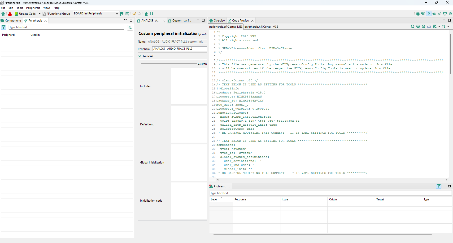
Peripherals view#
The Peripherals view contains a table showing a list of available peripherals on the currently selected processor that can be configured by the Peripherals tool. In case of multicore processors, the displayed peripherals are also core-specific.
Each instance of a peripheral (for example, UART0) occupies one row. First column contains peripheral name and a checkbox indicating whether the peripheral is used by any component instance.
Second column contains a name of component instance handling the peripheral. This name is customizable in the settings editor and it is used in generated code. The name of the component instance can’t contain spaces.
You can enable an instance by selecting the checkbox, or by clicking the switch in the settings editor of the component instance.
Disable a component instance by unchecking the checkbox.
Double-click the second column to open the Settings Editor for the component instance.
Right-click the the peripheral to open a shortcut menu. Several options are available in the shortcut menu.
Option |
Description |
|---|---|
Open |
Open the component instance in the Settings Editor. |
Open in another view |
Duplicate the component instance in the Settings Editor. |
Enable/Disable |
Enable/Disable the component instance. |
Add component instance |
Add a component instance to the peripheral. |
Initialized in user code |
Mark the peripheral as configured by user code (available on not configured peripherals). |
Edit comment |
Create/Edit custom notes for the component instance. |
Lock/Unlock editing of component instance |
Lock/Unlock the editing of the component instance. |
Save to use case library |
Create a template from the component instance. |
Documentation |
Display the documentation of the component instance, if available. |
Remove |
Remove the component instance from configuration. If more instances are in use, a confirmation window will allow you to select which instance you want to remove. |
Migrate |
Migrate the component to a different component type or to a component with a newer driver version. |
Move to |
Choose from available functional groups to move the component instance to. |
Copy to |
Choose from available functional groups to copy the component instance to. |
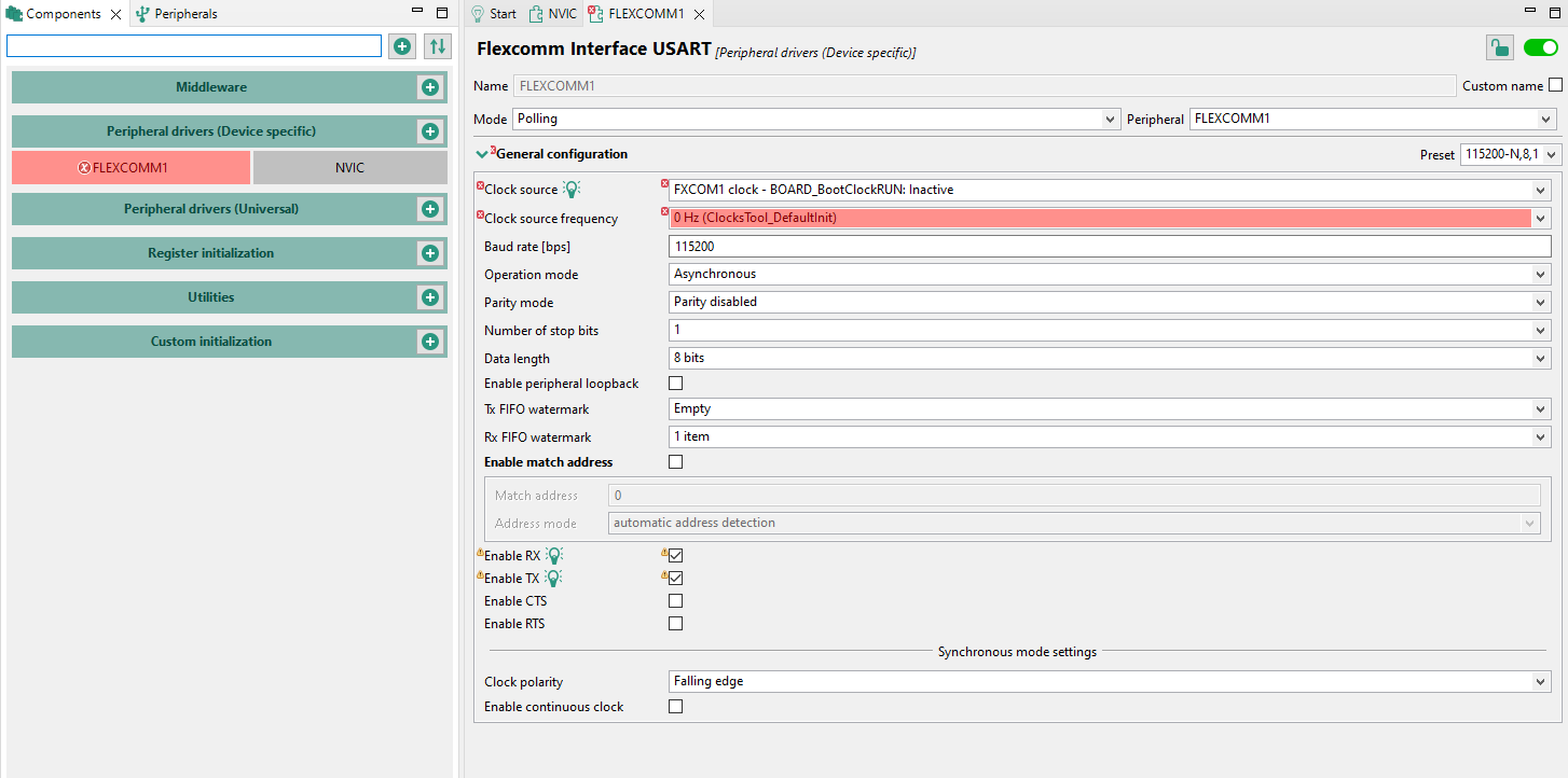
Settings Editor#
You can edit peripheral component settings in the Settings Editor. Open editors are shown in the central area of the screen, each with its own tab. Multiple editors can be opened at the same time. Changes done in the editor are immediately applied and kept even if the settings editor is closed. Settings that are disabled are highlighted in gray. In case that a component instance is disabled, all settings are highlighted in gray. Tooltips are displayed for all enabled settings when the mouse cursor is placed at settings.
To open Settings Editor, do the following:
Double-click the component instance in the Peripherals or Components view to display component instance settings.
Left-click the component in the Components view to display global settings of the component.
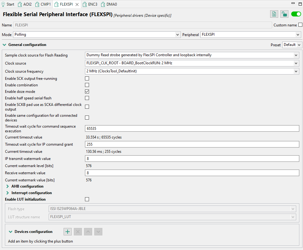
Settings editor#
Settings Editor header#
All components share the Settings Editor header. In the header, you can view and change component information, enable or disable the component, and view component documentation (where applicable).

Settings Editor header#
Header item |
Description |
|---|---|
Description |
Displays the configuration component title. |
Name |
Displays the component instance name. This name is used in the generated code in constants and function identifiers and is derived from the peripheral name. You can change it at any time by clicking the Custom name button and editing the field. |
Mode |
Displays the required usage for the component instance and influences available settings. Use the dropdown menu to change the mode (where applicable). |
Peripheral |
Displays the name of the peripheral to be associated with the component instance. Use the dropdown menu to change it. |
Documentation |
Click the button to view configuration component-specific documentation in the Documentation view. Not all configuration components are documented, therefore not all setting headers contain the Documentation icon. |
Lock editing |
Click the button to lock/unlock component editing. Source code will still be generated. |
Enable/disable component instance switch |
Use the switch to enable or disable selected component instance. By disabling the instance, you don’t remove it from the tools configuration, but prevent its inclusion in the generated code. |
Presets#
Settings are grouped to larger groups (config sets) that may provide presets with typical values. You can use these presets to quickly set the desired typical combination of settings or return to the default state.
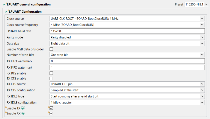
Quick selection example#
Settings#
Following setting types are available in the Settings Editor.
Boolean – Two state setting (yes/no, true/false).
Boolean setting example#
Integer, Float – Integer or float number.
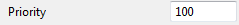
Integer/Float setting example#
String– Textual input. More than a single line can be supported.
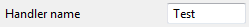
String setting example#
Enumeration – Selection of one item from list of values.

Enumeration setting example#
Set – List of values, multiple of them can be selected.
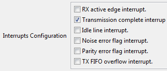
Set setting example#
Structure – Group of multiple settings of different types, may contain settings of any type including nested structures.
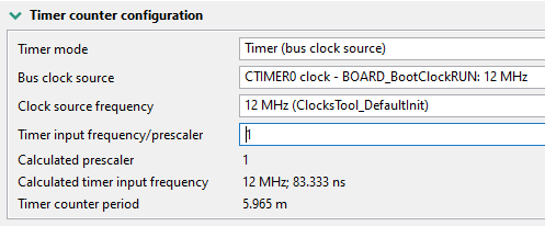
Structure setting example#
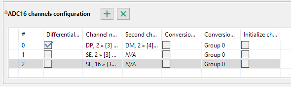
Array – Array of multiple settings of the same type – you can add/remove items. The array of simple structures may also be represented as a table grid, master-detail, tabs,and radio buttons.
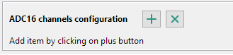
Array#
The ‘+’ button adds a new item at the end of array. To rearrange the position or delete an item, right-click the item and select one of the following options: Move up, Move down, Move to top, Move to bottom, or Remove. You can also copy-paste an array from one instance to another by right-clicking the array label and choosing Copy. You can then navigate to another instance array, right-click the table, and choose Paste to add it.
Note: The array can be copied and pasted to another configuration, including in the second running instance of Config Tools.
Array setting example#
Info– Read-only information for the user.

Info setting example#
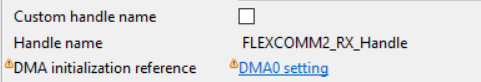
Info setting as link example#
File setting - Link/import an external settings file.

File setting#
Documentation view#
You can display component-specific documentation by opening the Documentation view.
Note: Not all components might have this option enabled.
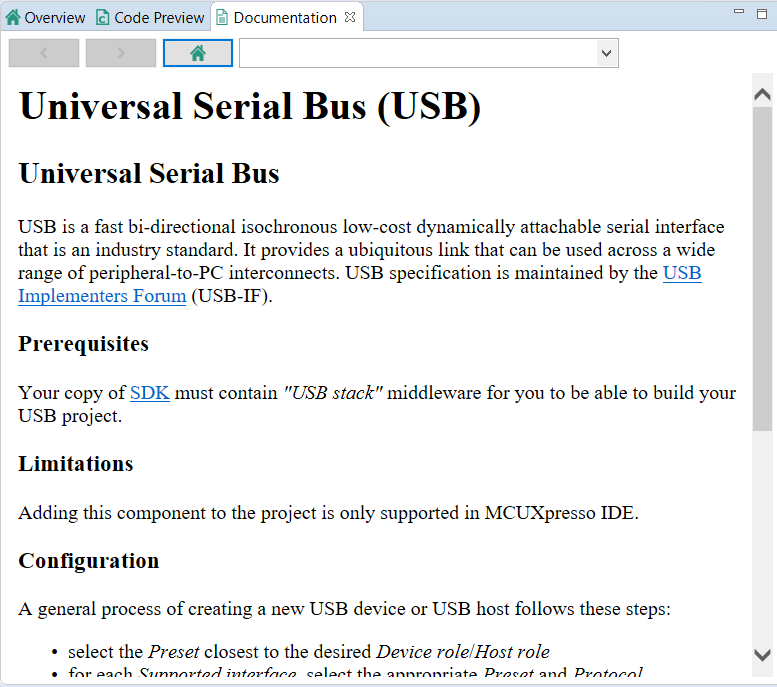
Documentation view#
You can open the Documentation view in several ways:
In the Peripherals view, right-click the peripheral checkbox and choose Documentation from the list.
In the Components view, right-click the component and choose Documentation from the list.
In the Settings Editor, click the Documentation button next to component name.
In the Settings Editor, click the question mark next to the settings label.
Component use case library#
In Peripherals tool, you can save, edit, and import/export component use cases for future use. Use cases are saved in a MEX format and can be viewed and modified in the Component use case library. The library displays all created/imported use cases by component type.
To open the Component use case library, Select Peripherals > Component use case library from the Menu bar.
To create a component use case, do the following:
Right-click an entry in the Peripherals or Components views.
Select Save to use case library from the context menu.
Enter the name and description in the Use case detail dialog.
Click OK.
Component migration to a different version#
Configuration components that generate configuration code for SDK components often require specific versions (or range of versions) of one or more SDK components.
The SDK component and its version that is expected for the proper function of the configuration component is visible when components are added to the selection dialog:
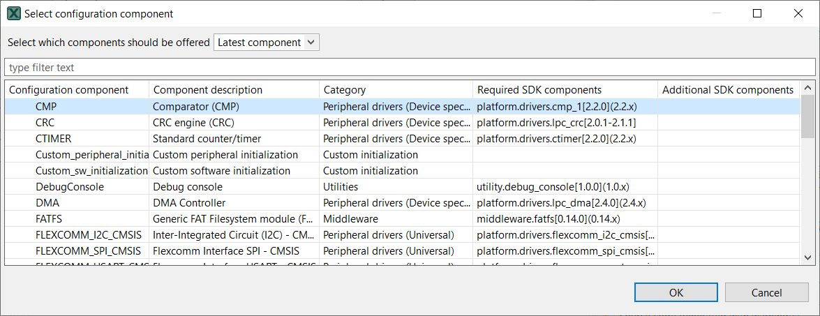
Component selection#
It is also visible in the tooltip in the Component view:
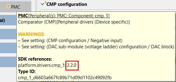
Tooltip in the Component view#
You can update the SDK components in the toolchain/IDE project.
When a configuration is open and the SDK component versions in the toolchain project do not match the version that is referenced in the configuration component, automatic migration is offered in the Component migration dialog. The migration can be also launched manually in the peripherals tool using the menu Peripherals > Migrate to other component versions.
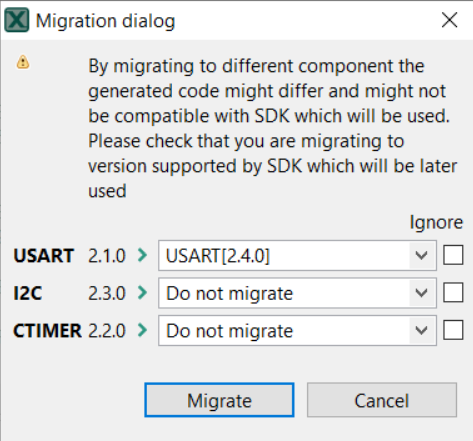
Migration dialog#
Each row in the dialog corresponds to one configuration component that can be migrated to other version. The dialog above displays the current version specified in the current configuration component and a combo box allowing you to select the new version that replaces the current one.
In standalone Config Tools, it is possible to migrate settings to any available version. In IDE/toolchain project mode, the combo box contains only the component with the version matching the SDK component currently used in the project.
The default selection in the toolchain-less configuration is “Do not migrate”. In the toolchain configuration, the default selection is the only version to which the migration can be performed. If “do not migrate” is selected, no changes are made to the particular component.
The Ignore checkbox prevents the component from the migration during next check.
After you confirm the dialog by selecting “Migrate”, the component is replaced by the component matching the selected version of the SDK component. The settings are migrated to the corresponding settings in the new version of the component, where it is possible.
If the new version of the component contains some new settings, these settings are filled with the default values. Check manually if the components are set properly.
The Migration result dialog is a dialog with the summary of the migration. It automatically opens after migration is successfully completed. This dialog contains the summary of events with various impact, that happened during the migration. It also contains a link, that opens the generated detail report in the HTML format, and a button that copies the path to the report into the system clipboard.
The generated Migration report contains the date and information about the configuration location, MCU, toolchain project in its header. It helps to identify to what configuration it is related. Below that is a table, that contains rows for each migration. A short description of the migration is provided. Each row has two columns where the first contains the path to the migrated setting and the second contains the description of the migration. Each row can have differently colored text, that indicates the importance of the message.
Problems#
The tool validates the settings and problems and errors are reported in the Problems view.
If there is an error related to the setting or component, an error decorator is shown next to the element containing an error.
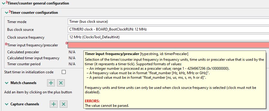
Error decorators#
In the case of a dependency error, a quick-fix button is displayed.

Quick fix 1#
Right-click the button to display a list of issues, then left-click the issue to display possible solutions.
Quick fix 2#
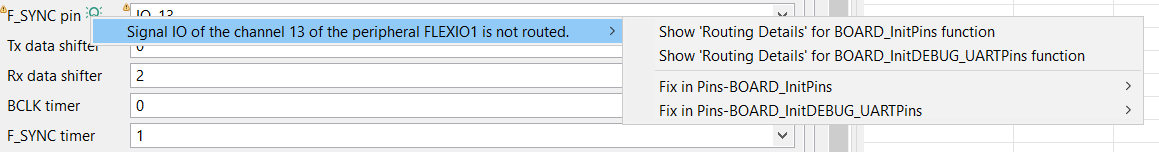
The problem can be quickly fixed even when reported from a table cell as the context menu contains the list of possible quick fixes (see register initialized SCTimer, for example LPC54114 Resources > Outputs setting).
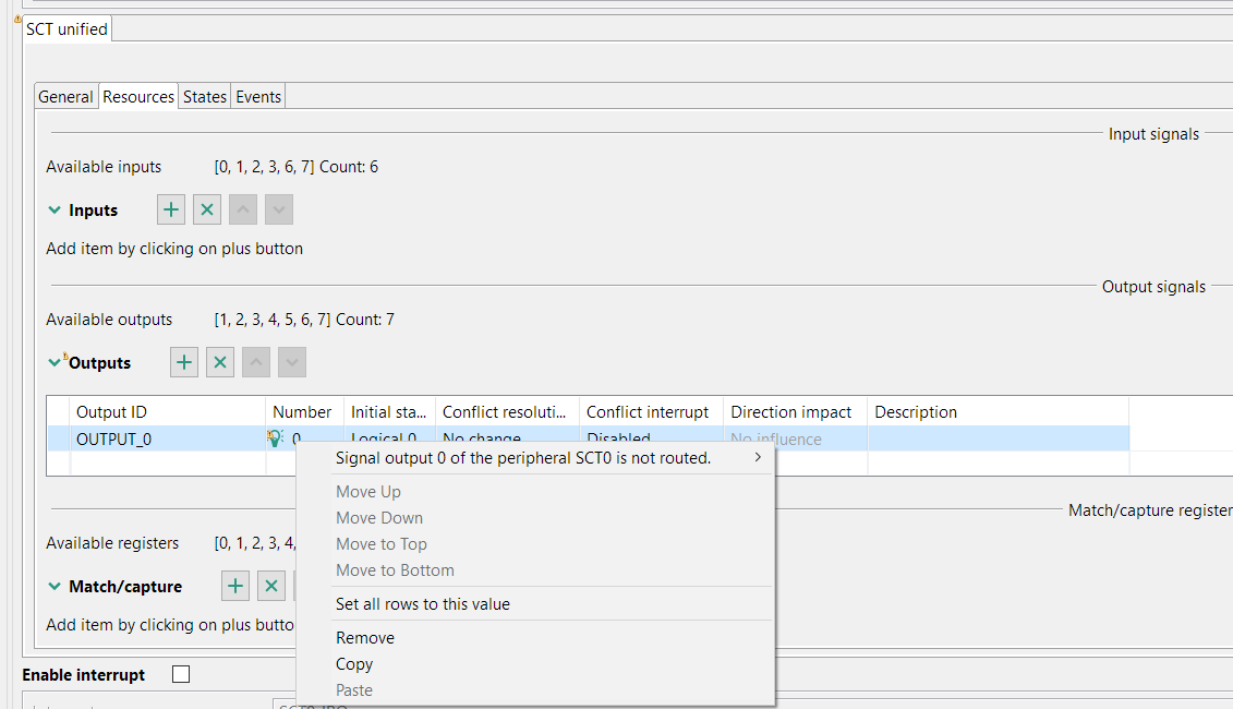
Quick fix 3#
Code generation#
If the settings are correct and no error is reported, the tool’s code generation engine instantly regenerates the source code. You can view the resulting code the Code Preview view of the Peripherals tool.
Code Preview automatically highlights differences between the current and immediately preceding iteration of the code. You can choose between two modes of highlighting by clicking the Set viewing style for source differences. You can also disable highlighting altogether from the same dropdown menu. Such features as Copy, Search, Zoom-in, Zoom-out, and Export source are available in the Code Preview view. The search can also be invoked by CTRL+F or from the context menu.
The Peripherals tool produces the following C files:
peripherals.c
peripherals.h
Note: For multicore processors, the peripherals.c/.h are generated for each core, containing functional groups associated with that core. It can be configured in functional group properties.
Note: Some components, such as the USB or FlexSPI, may generate additional output files.
These files contain initialization code for peripherals produced by selected configuration components including:
Constants and functions declaration in header file.
Initialized configuration structures variables (constants).
Global variables for the user application that are used in the initialization. For example, handles and buffers.
Initialization function for each configuration component.
Initialization function for each functional group. The name of the function is the same as the functional group name. It is prefixed by the “prefix” property if defined in the functional group dialog. These functions include execution of all assigned component initialization functions.
Default initialization function containing call to the function initializing the selected functional group of peripherals.
Note: The prefixes of the global definitions (defines, constants, variables, and functions) can be configured in the Properties of the functional group.
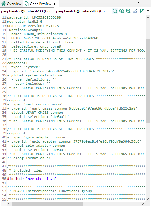
Code Preview#