Pins Tool#
Pins tool is an easy-to-use tool for configuration of device pins. The Pins tool software helps create, inspect, change, and modify any element of pin configuration and device muxing.
Pins tool#
Pins routing principle#
The Pins tool is designed to configure routing peripheral signals either to pins or to internal signals.
This routing configuration can be done in the following views:
Pins
Peripheral Signals
Package
Routing Details
Following two sections describe the two methods that you can use to define the routing path.
Beginning with pin/internal signal selection#
You can select a pin or an internal signal in the Routing Details view.
Select the pin/internal signal (Routed pin/signal).
Select one of the available Peripherals.
For the selected peripheral, select one of the available Signals.
Items in Peripheral column in Routing Details view have the following symbols:
Exclamation mark and default text color indicate that such item selection can cause a register conflict or the item does not support selected signal.
Exclamation mark and gray text color indicate that the item cannot be routed to the selected pin/internal signal. The item is available for different pin/internal signal using the same signal.
Note: In the Pins view and the Package view, you can configure only pins and not internal signals.
Routing of peripheral signals#
Peripheral signals representing on-chip peripheral input or output can be connected to other on-chip peripherals or to a pin through an inter-peripheral crossbar. You can configure this connection in the Routing Details view.
Three types of peripheral signal routing are available:
Routing the signal from the output of an internal peripheral (A) into the input of another internal peripheral (B)
The signal leads from the output of one internal peripheral (A) to the input node of another internal peripheral (B). In other words, signal leads from A to B (A > B). To configure a signal in this way, perform the following steps (PWM triggering ADC (PWM > ADC) used as example):
Add a row in the Routing Details view.
Select peripheral B from the drop-down list in the Peripheral column.
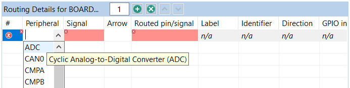
Selecting the peripheral (B)#
Select the input node of peripheral B from the drop-down list in the Signal column.
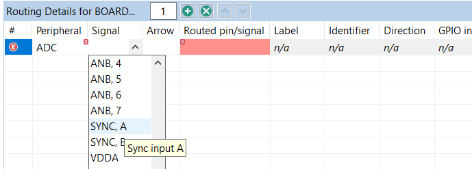
Selecting the input node (B)#
Select the output signal of peripheral A from the drop-down list in the Routed pin/signal column.

Selecting the output signal#
Once the configuration is done, the row looks like this:
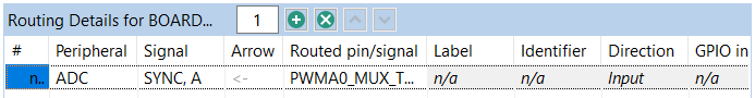
Result#
Note: It is necessary to select the ADC peripheral where the signal leads to (input in ADC). It is a limitation of the Pins tool that the signal is not listed for the PWM peripheral (output). Notice the direction of the signal in the Arrow column.
Routing the signal from a pin on the package to internal peripheral input signal through an inter-peripheral crossbar
Note: Only if a crossbar switch is present.
The signal leads from a pin on the package (XB_IN) connected through an inter-peripheral crossbar, to an internal peripheral (B) input node. In other words, the signal leads from XB_IN to B (XB_IN > B). To configure a signal in this way, perform the following steps (routing pin 55 using XB_IN6 to EVTG0 input A (XB_IN6 > EVTG0) used as example):
Add a row in the Routing Details view.
Select peripheral B from the drop-down list in the Peripheral column.
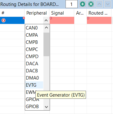
Selecting the peripheral (B)#
Select the input node of peripheral B from the drop-down list in the Signal column.
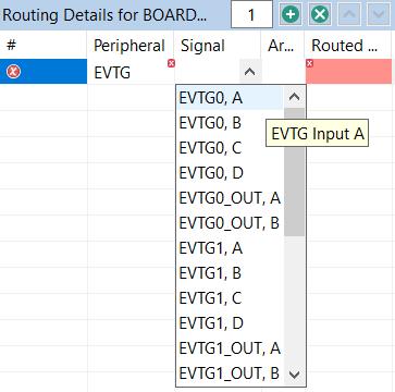
Selecting the input node (B)#
Select the XB_IN pin from the drop-down list in the Routed pin/signal column.
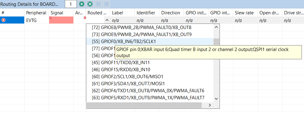
Selecting the pin#
Once the configuration is done, the row looks like this:
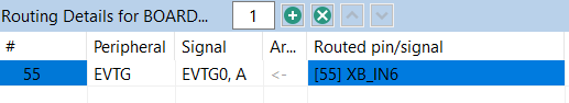
Result#
Note: In this example, GPIOF0 is multiplexed with XB_IN6, QTimerB channel 2 output/input and QSPI1 SCLK signal. In this case, the tool will automatically pick XB_IN6 for the pin as XB_IN6 is the only option to be routed to EVTG0 input A.
Routing the signal from internal peripheral (A) output to a pin via inter-peripheral crossbar
Note: Only if a crossbar switch is present.
The signal leads from internal peripheral (A) output to a pin connected through an inter-peripheral crossbar on the package (XB_OUT). In other words, the signal leads from A to XB_OUT (A > XB_OUT). To configure a signal in this way, perform the following steps (routing EVTG0 output to a pin 87 using XB_OUT4 used as an example):
Add a row in the Routing Details view.
Select peripheral A from the drop-down list in the Peripheral column.

Selecting the peripheral (A)#
Select the input node of peripheral A from the drop-down list in the Signal column.

Selecting the output signal (A)#
Select the XB_OUT pin from the drop-down list in the Route to column.
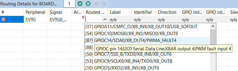
Selecting the pin#
Once the configuration is done, the row looks like this:
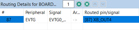
Result#
Note: In this example, GPIOC14 is multiplexed with XB_OUT4, SDA of I2C0 and fault4 of eFlexPWMA. In this case, the tool will automatically configure XB_OUT4 for the pin GPIOC14 (pin 87) as XB_OUT4 is the only option for EVTG0 output A.
Note: In some cases, multiple routings are configured by the same register change. When such routing is created, the user is offered an option to add the related routing to the functional group. Similarly, when a routing is removed, related routings are offered for removal.
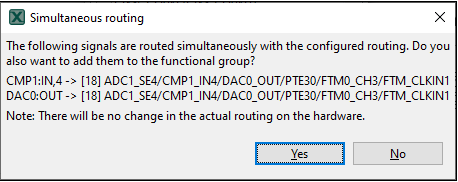
Simultaneous routing#
Example usage#
This section lists the steps to create an example pin configuration, which can then be used in a user project.
In this example, three pins (UART4_TX, UART4_RX and GPIO_2) routed on an MCIMX6Q-SDB-REV-B board are reconfigured to match changed (for example, customer modified) board design which is using UART4 pins instead of UART3 ones and must re-route and/or adjust electrical properties for a red LED pin, so then the tool generated files with application modifying the default board configuration.
Create new configuration for MCIMX6Q-SDB-REV-B board.
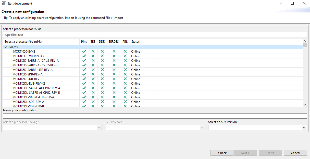
Create a new configuration#
After the tool opens, the created configuration select functional group ‘init_uart_pins’ in the toolbar drop-down to show Routed Pins for it.
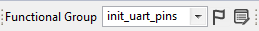
Select function#
To change original RX/TX pins routing from UART3 to UART4 you must change configuration in Peripheral and Route to columns of the Routed Pins view for init_uart_pins selection and change pins configuration to re-route the RX/TX pins to different ones for UART4 as required in modified board design.

Routed Pins view#
You can also adjust electrical properties configuration for these pins on the right side of the table in specific property column selection.
To change configuration of red LED pin routed originally to GPIO_2 pad, you must to select functional group ‘init_gpio_pins’.
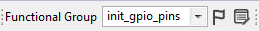
Select function#
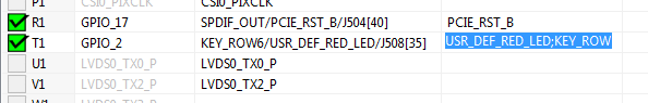
Then use filtering in the Routed Pins view to search configuration for “USR_DEF_RED_LED” to display simplified table content to easily modify current GPIO_2 pin routing selection.
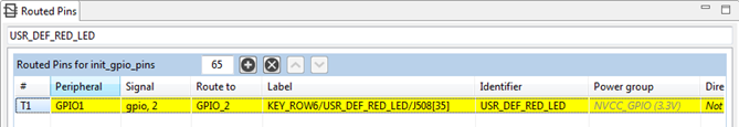
Routed Pins view#
You can then adjust either electrical properties or re-route the pin to a different one if required in your modified design.
The Pins Tool automatically generates the source code of imx6q-board.dtsi, pin_mux.c and pin_mux.h in the Code Preview view on the right.
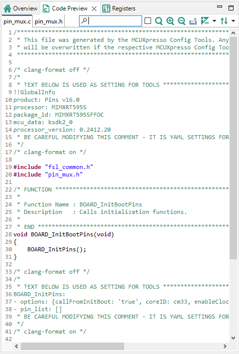
Generated sources#
You can now copy-paste the content of the source(s) to your application or IDE. Alternatively, you can export the generated files. To export the files, click Export button on the right up corner of Code Preview view or select the menu File > Export, in the Exportdialog expand the tree control for the Pins Tool and select the Export Source Files option.
Note: Tool generated board-oriented device tree (DTS) DTSI file is only a snippet and not a full device tree file content. There are just basic device tree elements, initial skeleton, and processor-specific “pinfunc.h” includes together with functional groups of fsl, pins = >…> content definitions which provide the initial IOMUXC module configuration according to the tool UI defined pin routing and functional configurations. Content itself must be manually merged together with existing Linux BSP device tree file(s) in order to apply the tool generated pins configuration. This tool also does not generate nor export processor-specific “pinfunc.h” file that is containing definition of all supported DTS pin functional configuration macros. This file is not purposely integrated within the tool output because it is a part of separate Linux BSP support package deliverables.
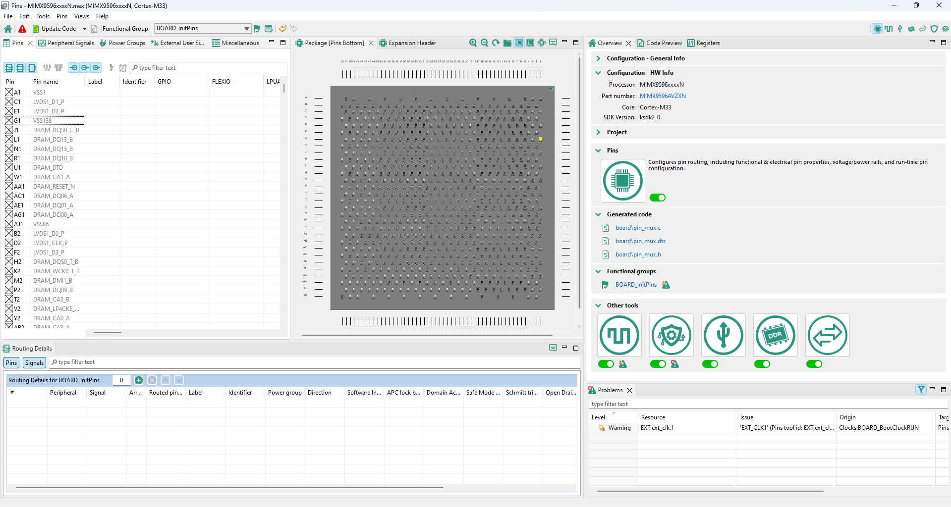
User interface#
The Pins tool consists of several views.
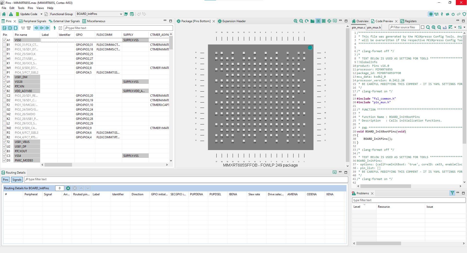
Pins tool user interface#
Pins view#
The Pins view shows all the pins in a table format.
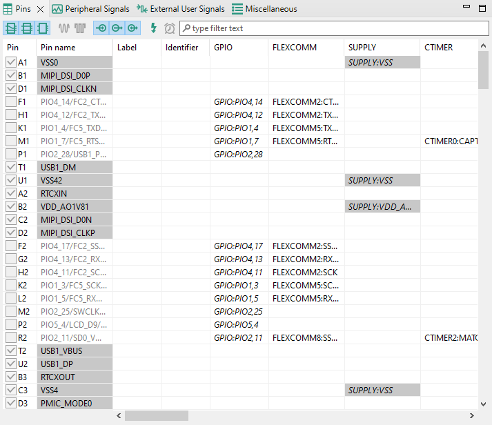
Pins table view#
This view shows the list of all the pins available on a given device. The Pin name column shows the default name of the pin, or if the pin is routed. The next columns are optional. They are Label, Identifier, External User Signals and Expansion header connections (One column for each expansion header). The pin name is changed to show the appropriate function for the selected peripheral if routed. The next column of the table shows peripherals and signals and pin name(s) on a given peripheral. Peripherals with a few items are cumulated in the last column.
To route/unroute a pin to the given peripheral, select the relevant cell in the Pin column. Routed pins are highlighted in green. If a conflict in routing exists, the pins are highlighted in red.
Gray background color in the Pin name column indicates that the pin/peripheral is dedicated. It is routed by default and has no impact on the generated code.
Every routed pin appears in the Routed pins table.
When multiple functions are specified in the configuration, the Pins view shows pins for the selected function primarily. Pins for different functions are shown with light transparency and cannot be configured until switched to this function.
Select a row to open a drop-down list that offers the following options:
Route/Unroute the pin.
Highlight the pin in the Package view.
Set the label and identifier for the pin.
Add a comment to the pin. You can later inspect the comment in the Code Preview view.
Tip: The option to route more signals to a single pin is indicated by an ellipsis (…). Select the cell to open a dialog to choose from multiple available signals. The dialog also displays which signals are routed by default.
Package#
The Package view displays the processor package. The processor package provides an overview of the package including resource allocation.
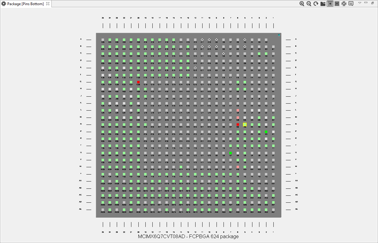
Processor package#
This view shows package overview with pins location. In the center are the peripherals.
To highlight the pin/peripheral configuration in the Pins and Routing Details views, right-click the pin or peripheral and select Highlight.
For BGA packages, use the Resources icon to see them.
Green color indicates the routed pins/peripherals.
Gray color indicates that the pin/peripheral is not routed.
Dark Gray color indicates that the pin/peripheral is dedicated. It is routed by default and has no impact on generated code.
The view also shows the package variant and the description (type and number of pins).
The following icons are available in the toolbar:
Icon |
Description |
|---|---|
|
Zoom in package image. |
|
Zoom out package image. |
|
Rotate package image. |
|
Show pins as you can see it from the bottom. This option is available on BGA packages only. |
|
Show pins as you can see it from the top. This option is available on BGA packages only. |
|
Show resources. This option is available on BGA packages only. |
|
Switch package. |
|
Package legend. |
|
Select the information displayed as pin labels. This option is not available on BGA packages. |


Note: Depending on the processor package selected, not all views are available.
The Switch package icon launches Switch package for the Processor.
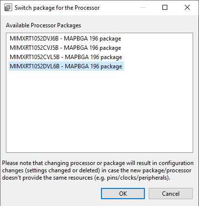
Switch package#
The Switch package for the Processor window shows list of available processor packages, showing package type and number of pins.
Peripheral Signals view#
The Peripheral Signals view shows a list of peripherals and their signals. Only the Peripheral Signals and Pins view show the checkbox (allocated) with status.
Color code |
Status |
|---|---|
|
Error |
|
Configured |
|
Not configured |
|
Warning |
|
Dedicated: Device is routed by default and has no impact on the generated code. |


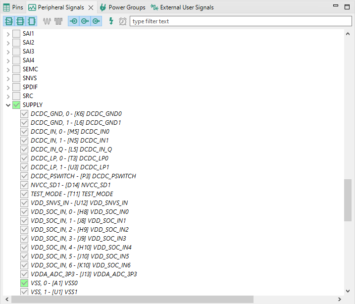
Peripheral Signals view#
Use the checkbox to route/unroute the pins.
To highlight the pin/routing configuration about the peripheral in the Package and Routing Details views, right-click the signal and select Highlight.
To route/unroute multiple pins, click the peripheral and select the options in the Select signals dialog.
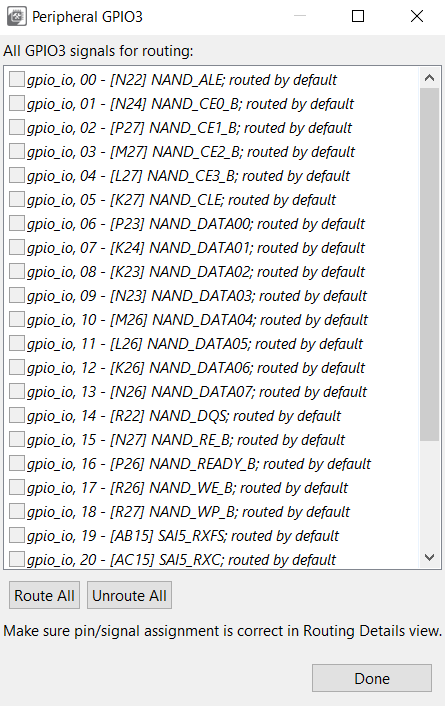
Select signals dialog#
Filtering in the Pins and Peripheral Signals views#
The following image illustrates the filtering controls in the Pins and Peripheral Signals views.

Filtering Controls#
Type any text to search across the table/tree. It will search for the pins/peripheral signals containing the specified text. You can also use wildcards “*” and “?” to help you filter results you want. Use “space” to search for multiple strings at the same time.
Routing Details view#
In the Routing Details view, you can inspect and configure routed pins and internal signals. You can also configure the electrical properties of pins and view them. It displays the pad configuration available in a configuration where each pin is associated with the signal name and the function.
The table is empty when a new configuration is created, which means no pin is configured. Each row represents the configuration of a single pin and if there are no conflicts, then the code is immediately updated. For Boards/Kits, the pins are routed already.

Routing Details#
Add a row with the Add new row button in the view toolbar.
Configure the pin/signal by selecting the Peripheral first, then the required Signal, and finally, the pin to Route to.
Use the columns in the right side of the table to configure the electrical features.
You can also use the Pins and Peripheral Signals views to route pins and peripheral signals and view/modify the configuration in the Routing Details view. If the feature is not supported, n/a is displayed.
To highlight peripheral/pin information in the Package and Pins views, right-click the row and select Highlight.
To filter rows, type the text or the search phrase in the filter area in the view toolbar.
Note: When you enter the search text, it also searches the text in the full pin names display rows that contain the search text.
To display pins or signals only, use the Pins and Signals buttons in the view toolbar.
To add a row to the end of table, click the Add new row button.
To remove the selected row, click the Delete the selected row button.
To delete a specific row or insert a new row at a given position, right-click and use the dropdown list commands.
To add a specific number of rows, enter the number in the field.
To clear the table, type 0.
To change the order of the rows, use the arrow icons to move one row up or down.
To filter table entries by text, enter the text string in the type filter text field.
To copy the row, right-click any cell in the row and select Copy. You can later paste the copied row into the Routing Details view of another functional group or configuration by right-clicking the table and choosing Paste.
The gray background indicates read-only items.
Properties configured in Routing Details view#
The properties of pins and internal signals that can be configured are shown in dedicated columns. The properties include:
Common properties available for all pins and internal signals
# - Package pin number/coordinate
Peripheral - Name of the selected peripheral module
Signal - Name of the selected peripheral signal/signal function
Arrow - Arrow indicating input, output, input/output, or not specified direction of the signal
Routed pin/signal - Name of the pin or internal signal
Label - Pin label with max length of 128 characters; By submitting an empty label the identifier is deleted as well
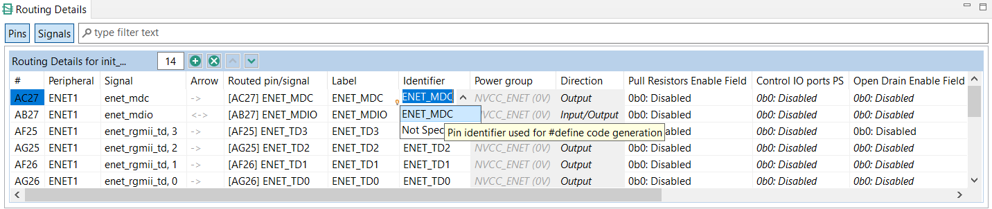
Identifier - Pin identifier used for #define code generation
Direction - Pin direction
General-Purpose Input Output (GPIO) properties available only for GPIO pins
GPIO initial state - GPIO output initial state. It is available only if pin direction is set to output.
GPIO interrupt - Configuration of interrupt request for the pin. It is available only if the pin direction is set to input.
Processor-specific properties
Properties that may differ for different processors, for example configuration of pull ups, open drain, drive strength, slew rate, power groups
Tip:
Click the Routing Details Legend button in the top-right corner of the view to display a dialog explaining all the properties and their values.
Generation of initialization code
The Pins tool generates initialization code only for pins and internal signals configured in the Routing Details view. Generally, initialization code is generated always if it is necessary for proper routing of the pin or internal signal to selected peripheral signal. On the other hand, the code related to the direction, GPIO functionality or processor-specific properties is automatically optimized out in the following cases:
The user does not explicitly select a value of a property. It is signalized by the italic font of the value. It is the default state after adding a pin or internal signal to the Routing Details view. The displayed value shows either the value set by another configuration of the same pin in the same function or in a function called from the default initialization function. When there is no such configuration, the displayed value matches the after-reset state. To generate the code even if the value is the same as the default value, select the value from the drop-down menu: the value is shown with normal font and code is generated. To return to the default value select “No init” from the drop-down menu: the value is again shown with italic font and no code is generated.
A “Not specified” value is selected in case of the direction property.
Additionally, it is possible to force generation of full initialization code of all properties using “Full pins initialization option” in Functional groups. If this option is enabled, it is not possible to use the “No init” value from the drop-down menu and the initialization code is generated unless the “Not specified” value is selected (for direction only). For more information about the “Full pins initialization option” option, refer to the Functional group properties section in this documentation.
Validation of routing
The Pins tool automatically performs validation of the selected properties. An error is shown for a property in the Routing Details view in the following cases:
The value of the property is in conflict with the value of other property. Typically conflicts arise when two pins or internal signals configures same register and bitfield with different initialization value. To resolve the conflict, the configuration of one of the pins or internal signals have to be changed.
There is no after-reset value specified for the property. In this case the error indicates that the user has to select the value of the property or “Not specified” to indicate that the property can be ignored by the tool.
The property has to be set by the user. In this case, the “No init” or “Not specified” are not available and the user must decide what value will be used. A typical use case is when routing of the internal signal would not be complete without such selection or when it is necessary to confirm by the user the intended usage of the pin or signal.
Labels and identifiers#
You can define the label of any pin that can be displayed in the user interface for ease of identification.
Boards and kits have predefined labels. However, it is also possible to define a pin label listed in the Pins and Routing Details views.
To set\update the Labels and Identifier columns visibility, select Edit> Preferences from the Menu bar, and select the Show pin label & identifier table columns (Pins tool) checkbox.
Labels and Identifiers#
The pin identifier is used to generate the #define in the pin_mux.h file. However, it is an optional parameter. If the parameter is not defined, the code for #define is not generated. Also, you can define multiple identifiers, using the “;” character as a separator. You can also set the identifier by typing it directly into the cell in the Identifier column in the Routing Details views.
Pin identifier#
In this case, it is possible to select from values if the pin is routed. See the Identifier column in the Routing Details view.

Identifier in Routing Details table#
A check is implemented to ensure whether the generated defines are duplicated in the pin_mux.h file. These duplications are indicated in the identifier column as errors.
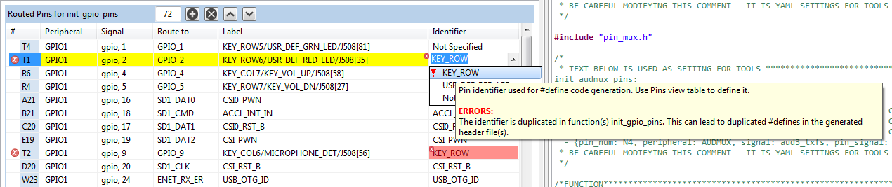
Identifier errors#
By typing a text into the Identifier column, you can define a new identifier for the pin. It is automatically used only in the selected routing. Available identifiers can be revised in a dialog invoked from a context menu or in the Pins view.
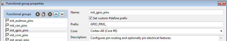
Pins macros prefix#
If multiple functions are used, each individual function can include a special prefix. Check the Pins > Functional Group Properties > Set custom #define prefix checkbox to enter prefix of macros in a particular function used in the generated code of the pin_mux.h file. Entered prefix text must be a C identifier. If unchecked, the Function name is used as a default prefix.
Expansion Header#
In the Expansion Header view, you can add and modify an expansion header configuration, map the connectors, and route the pin signals. You can also import and apply an expansion board to the header.
Certain boards, such as LPCXpresso55S69, come with preconfigured expansion headers.
Expansion header#
The expansion header is not automatically preset for every supported device. If the header is not preconfigured, follow these steps to create and modify an expansion header configuration:
Open the view by selecting Views > Expansion Header from the Toolbar.
Add a header by selecting the Add button in the view toolbar.
In the Add New Expansion Header window, select the Header type from the drop-down list.
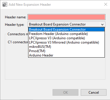
Adding new expansion header#
Name the header and map the connectors.
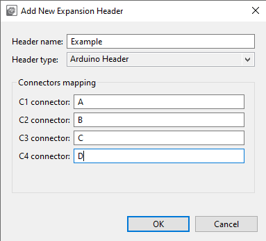
Adding new expansion header#
Select OK.
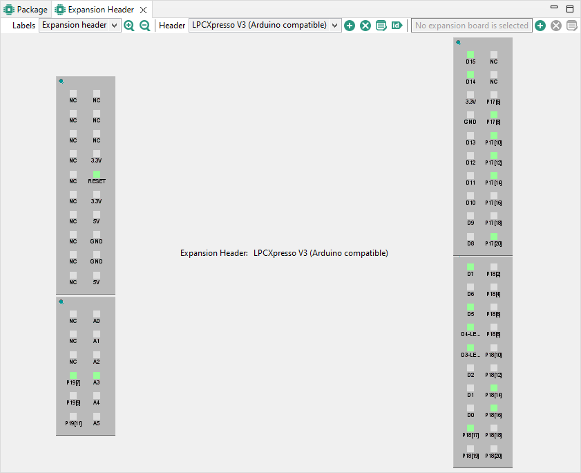
Expansion Header view now displays the connector layout. You can point your cursor over the pins to display additional information. Right-click the pin to display a shortcut menu of additional options.
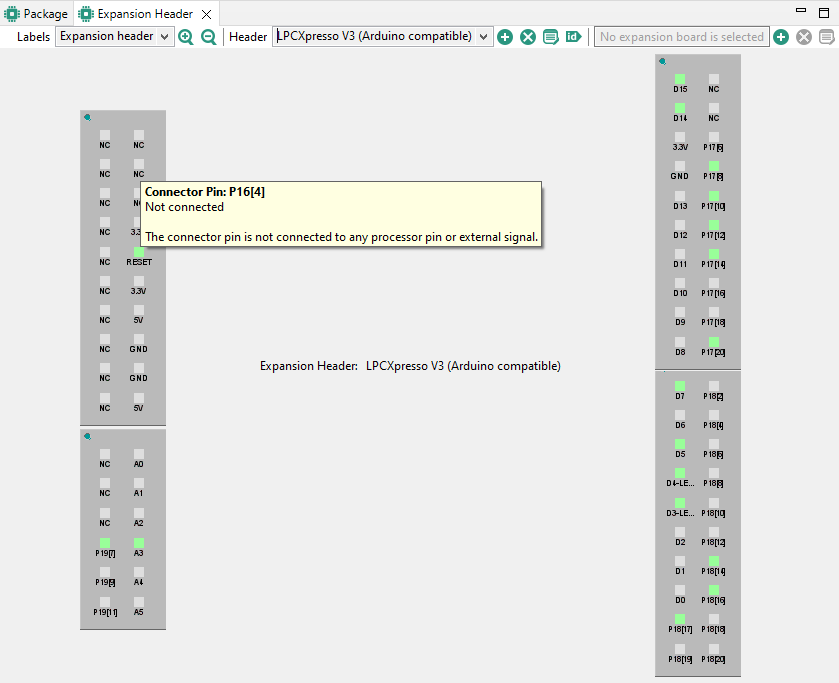
Expansion header#
To map the header pin to processor pin, right-click the header pin and select Connect.
In the Connector Pin dialog, select the processor pin/external signal from the list and click OK.
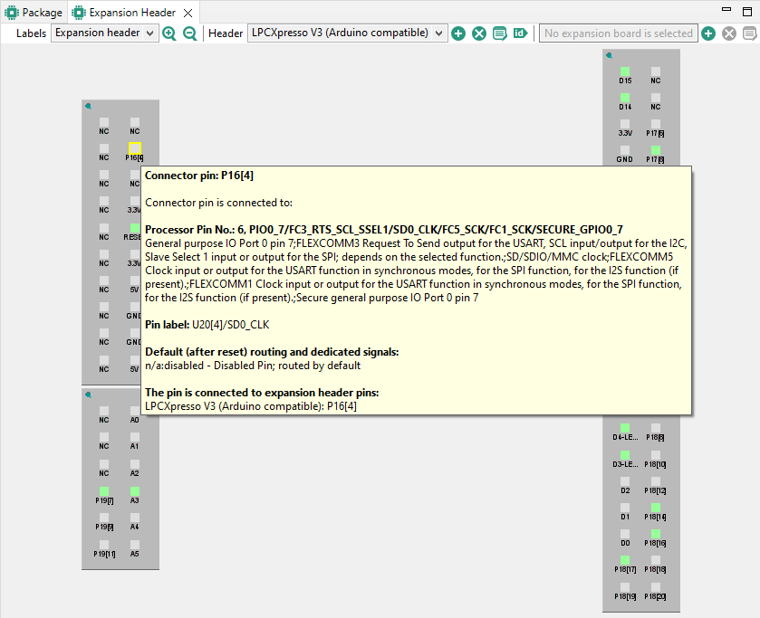
Connected pin#
To route the pin, right-click the header pin and select Route.
In the Pin dialog, select the signal from the list and click OK.
The connector pin is now routed.
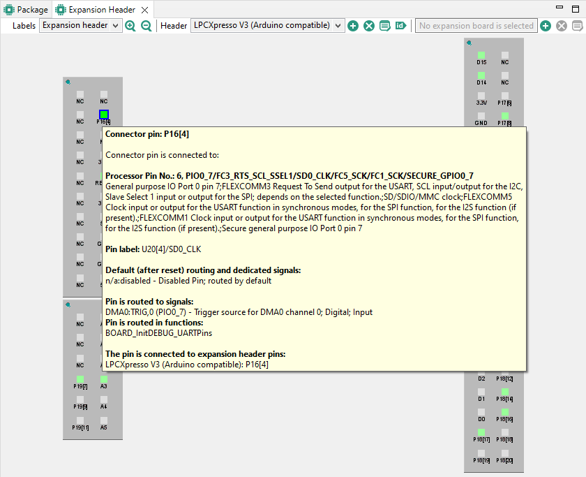
Routed pin#
You can create more than one expansion header configuration. Switch between the configurations in the view’s drop-down list.
To highlight the pin/routing configuration in the Pins and Routing Details views, right-click the connector pin and select Highlight.
Modify the configuration parameters at any time by selecting the Edit button. Information in the Pins view is updated automatically. Pin connections between the header and the processor and their labels can be locked to prevent any modifications.
Remove a configuration by selecting the Remove button.
Use the Label drop-down list to switch between display information for header, board, and routing.
The ID button allows setting expansion header pin labels as processor pin identifiers. Upon user selection, the new identifiers can be also explicitly selected.
Expansion Board#
In the Expansion Header view, you can also apply an expansion board to an already created expansion header. The expansion board configuration can be imported into Pins tool in the form of an XML file. Based on the chosen processor, the tool will then recommend adequate routing.
Note: Only a single expansion board can be configured per expansion header.
In the Expansion Header view, click the Apply expansion board to the selected header. Alternatively, select Pins > Apply expansion board from the Menu bar.
In the Apply expansion board dialog, click Browse to locate the XML file with expansion board information and click OK.
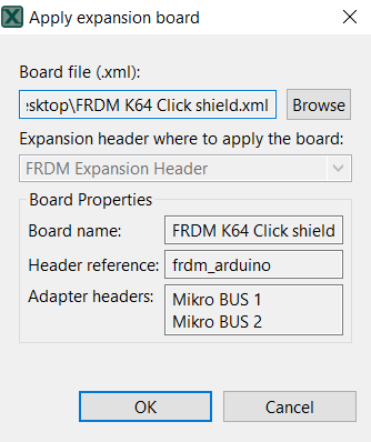
Apply expansion board#
Click OK to apply the expansion board.
On the next page, choose if you want to create a new functional group for the expansion board, or modify an existing functional group. In the latter case, use the dropdown list to select from available functional groups.
In the Expansion Board Routing table, inspect the suggested routing of expansion board pins. If you want to change the route of a pin, click the pin cell in the Route column and select the signal in the Connector pin dialog and click Done.

Expansion board routing#
Choose how you want to populate identifiers for code. Following options are available:
Expansion header names
Expansion board names
None
Click Apply to apply the settings.
You can change the expansion board signal routing at any time by clicking the Configure routing for expansion board button in the Expansion Header view.
Power groups#
If your processor supports power groups, an additional tab will appear next to Pins and Peripheral Signals.
Note: This feature is not supported for all devices.
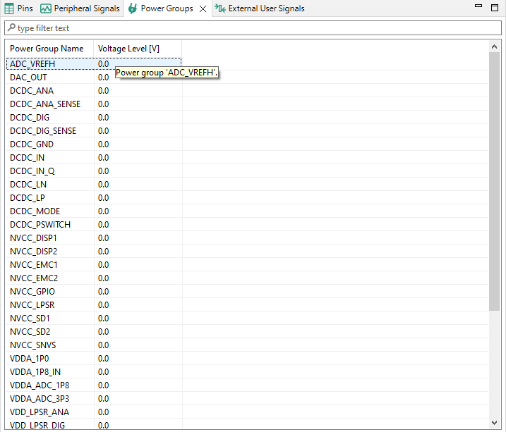
Selecting power group#
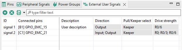
External User Signals view#
This view allows the user to define a custom description of the signals. An External User Signal has a defined unique ID within the table, pins to which it is connected, and any amount of additional text information. All of it can be customized.
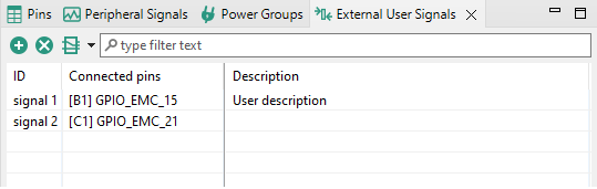
External User Signals view#
Connecting to a pin(s) can be done from a context menu of the selected signal. Multiple pins can be connected to the signal as well as multiple signals can be connected to the pin. When some signals are defined, the External User Signals column is added to the Pins view. The connection between pins and signals can be also done from there.
Additional columns can be specified using the table header context menu.
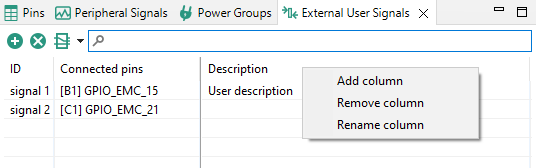
External User Signals header context menu#
The button with the Routing Details view icon can be used to add routed pins to the table or to display columns from Routing Details view in the External User Signals view.
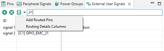
External User Signals view#
The Add Routed Pins option collects routed pins from all functional groups and adds them to the table when they are not already present. A new signal is created for each added pin.
Select Routing Details Columns to open a dialog with Routing Details columns. The selected columns will be displayed in the table. Those columns are read-only and they always reflect actual values in the Routing Details view for all functional groups.

Routing Details columns dialog#
Routing Details table#
When needed, External User Signals can be also exported to CSV and then imported to another configuration. Merging of signals is not supported so when some signals are defined for the configuration, they are replaced by imported signals.
Miscellaneous view#
This view contains Generate extended information into the header file (previously located in Configuration preferences) and possible processor specific settings.
When the Generate extended information into the header file option is selected, the extended information is generated into the header file. For projects created in earlier MCUXpresso versions, this option is selected by default.
When option Automatically select property value for a new routing is set, the after-reset state is explicitly set for every electrical property of a new routing.
Functions#
Functions are used to group a set of routed pins, and they create code for the configuration in a function which then can be called by the application.
The tool allows to creates multiple functions that can be used to configure pin muxing.
The usage of pins is indicated by 50% opacity in Pins, Peripheral Signals, and Package views. Each function can define a set of routed pins or re-configure already routed pins.
When multiple functions are specified in the configuration, the package view primarily shows the pins and the peripherals for the selected function. Pins and peripherals for different functions are shown with light transparency and cannot be configured, until switched to this function.
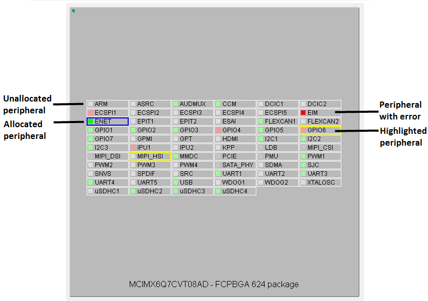
Highlighting and color coding#
You can easily identify routed pins/peripherals in the package using highlighting. By default, the current selection (pin/peripheral) is highlighted in the Package view.
The pin/peripheral is highlighted by yellow border around it in the Package view. If the highlighted pin/peripheral is selected, then it has a blue border around it.
Red indicates that the pin has an error.
Green indicates that the pin is muxed or used.
Light gray indicates that the pin is available for mux, but is not muxed or used.
Dark gray indicates that the pin/peripheral is dedicated. It is routed by default and has no impact on generated code.
Highlighting and color coding#

BGA package on pins side#

Pins conflicts#
Warnings#
Package view
Click the peripheral or use the pop-up menu to highlight peripherals:
and all allocated pins (to selected peripheral).
or all available pins if nothing is allocated yet.
Click the pin or use the pop-up menu to highlight the pin and the peripherals.
Click outside the package to cancel the highlight.
Peripherals / Pins view
The peripheral and pin behaves as described above.
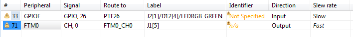
Errors and warnings#
The Pins Tool checks for any conflict in the routing and also for errors in the configuration. Routing conflicts are checked across all INIT functions (default initialization functions). It is possible to configure different routing of one pin in different functions (not INIT functions) to allow dynamic pins routing reconfiguration.
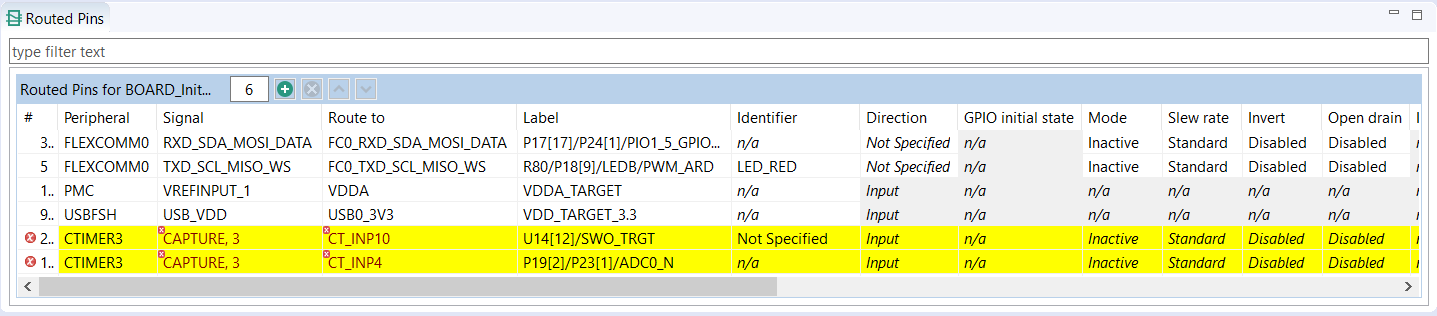
Error and warnings#
If an error or warning is encountered, the conflict in the Routing Details view is represented in the first column of the row and the error/warning is indicated in the cell, where the conflict was created. The last two rows in the figure above show the peripheral/signal where the erroneous configuration occurs. The detailed error/warning message appears as a tooltip.
For more information on error and warnings color, see the Highlighting and Color Coding section.
Incomplete routing#
A cell with incomplete routing is indicated by a red background. To generate proper pin routing, click the drop-down arrow and select the suitable value. A red decorator on a cell indicates an error condition.
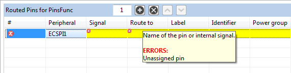
Incomplete routing#
The tooltip of the cell shows more details about the conflict or the error, typically it lists the lines where conflict occurs.
You can also select Pins > Automatic Routing from the Main menu to resolve any routing issues.
Note: Not all routing issues can be resolved automatically. In some cases, manual intervention is required.
Power groups voltage level conflicts#
The Pins tool provides information about possible voltage level conflicts when the peripheral signals routed pins are configured from a different power groups and the power groups have different voltage level value set in Power groups view.
In case of a potential voltage level conflict, a warning is displayed - a useful feature for hardware board designers.

Power group view#
Code generation#
If the settings are correct and no error is reported, the code generation engine instantly regenerates the source code. You can view the resulting code the Code Preview view of the Pins tool.
Code Preview automatically highlights differences between the current and immediately preceding iteration of the code. You can choose between two modes of highlighting by clicking the Set viewing style for source differences. You can also disable highlighting altogether from the same dropdown menu. Such features as Copy, Search, Zoom-in, Zoom-out, and Export source are available in the Code Preview view. The search can also be invoked by CTRL+F or from the context menu.
For multicores, the sources are generated for each core. Appropriate files are shown with @Core #{number} tag.
Note: The tag name may be different depending on the selected multi-core processor family/type.
You can also copy and paste the generated code into the source files. The view generates code for each function. In addition to the function comments, the tool configuration is stored in a YAML format. This comment is not intended for direct editing and can be used later to restore the pins configuration.
Note: Code Preview view contains the Export button and possibility of exporting sources - link to export wizard - Pins Tool > Export Source Files option-allowing export sources per used cores in multi-core enabled configuration.
YAML configuration contains configuration of each pin. It stores only non-default values.
Tip: For multicore processors, it will generate source files for each core. If processor is supported by SDK, it can generate BOARD_InitBootPins function call from main by default. You can specify “Call from BOARD_InitBootPins” for each function, in order to generate appropriate function call.
Using pins definitions in code#
The Pins tool generates definitions of named constants that can be leveraged in the application code. Using such constants based on user-specified identifiers allows you to write code which is independent of configured routing. In the case you change the pin where the signal is routed, the application will still refer to the proper pin.
For example, when the LED_RED is specified an identifier of a pin routed to PTB22, the following defines are generated into the pin_mux.h:
**\#define** BOARD_LED_RED_GPIO GPIOB /*!<@brief GPIO device name: GPIOB */
**\#define** BOARD_LED_RED_PORT PORTB /*!<@brief PORT device name: PORTB *'/
**\#define** BOARD_LED_RED_PIN 22U /*!<@brief PORTB pin index: 22 */
The name of the define is composed from function group prefix and pin identifier. For more details, see Functional groups and Labels and identifiers sections.
To write to this GPIO pin in application using the SDK driver (fsl_gpio.h), you can, for example, use the following code referring to the generated defines for the pin with identifier LED_RED:
GPIO_PinWrite(BOARD_LED_RED_GPIO, BOARD_LED_RED_PIN, true);
Full initialization of pins#
In some cases, the default values are not reliable, as there may be code running before the application that modifies the pin configuration (for example, a bootloader). The option Full initialization of pins ensures that the initialization is fully done even for items that use after-reset state. This option is specific for each Functional group allowing to force full initialization of routing. Full initialization of pins is not enabled by default. When enabled, the electrical properties of existing routing are changed. The values in italics are changed to explicit values corresponding with them. When the option is disabled, the pins tool removes initialization of values that match the “No init” state.
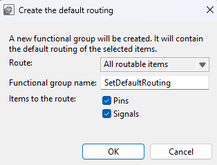
Create Default Routing#
If necessary, it is possible to create a new functional group that will route default signals to pins and internal signals. The functionality is available in Pins > Create Default Routing. There the user can select:
Whether all pins and signals will be routed, or only the ones that are not routed in other functional groups.
The name of the new functional group.
Whether the routing is created for pins and/or internal signals.
In the created functional group, the Full initialization function of the pins feature will be set. The electrical properties of pins will be set to their after-reset state.
Create the Default Routing#