SerDes Tool#
This section provides information about the SerDes Tool.
Introduction#
This section introduces the SerDes tool (SerDes stands for Serializer/Deserializer) that is an embedded component of Config tools for i.MX and supports the LX2, LA, and i.MX 95 processor families.
The SerDes tool provides two main functionalities: configuration and validation.
Note: The SerDes tool is provided as it is to aid customer capabilities of evaluating, debugging, and optimizing their designs. The results, or any part thereof, provided by the tool cannot be under any circumstances seen as a substitute for the traditional validation and compliance methods, which must be performed to declare compliance of the designs with the respective IP standards.
Create a SerDes tool project#
To use the SerDes tool, create a project.
To create a SerDes tool project, follow these steps:
Open the Config tools for i.MX.
Choose Create a new standalone configuration for a processor, board, or kit and click Next.
From Processors, choose one of the devices with SerDes tool support and click Finish.
Click the SerDes tool icon to open the SerDes tool view
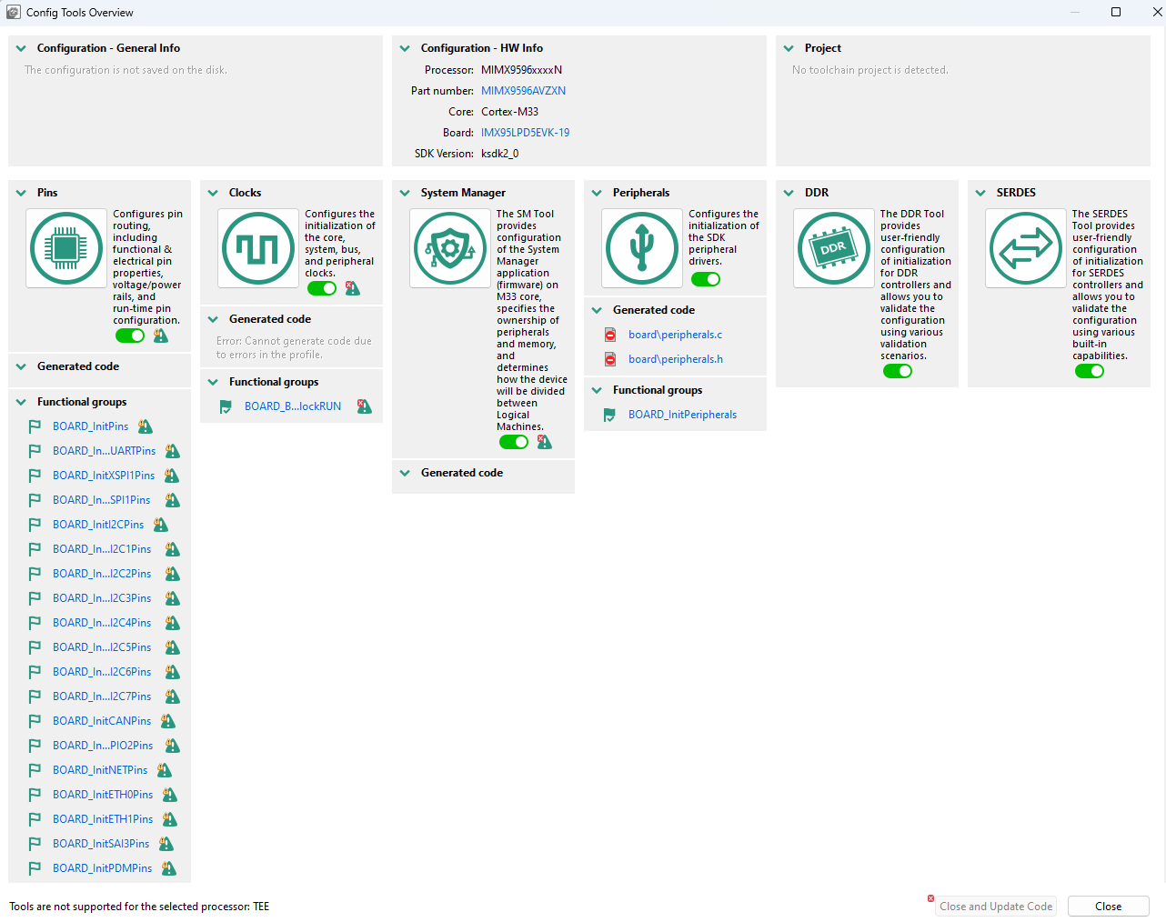
Config Tools overview#
To use the SerDes tool, the Disclaimer must be accepted.

Disclaimer#
SerDes configuration#
The SerDes configuration provides a user-friendly graphical interface to configure the SerDes interface and other associated sub-systems. It can be used to change the SerDes configuration when a different protocol is used and to optimize the parameters associated with signal integrity.
An SoC can have several SerDes modules. Each SerDes module is organized into entities called lanes. The number of lanes varies with the device type.
Configuring SerDes means effectively configuring its lanes and involves:
Protocol and speed – define what kind of traffic and at which speed the lane can operate with
PLL used by the lane
Transmit and receive equalization and electrical parameters. These are more in-depth configuration parameters that can affect the quality of the transmission on the lane
Lane configuration#
The Lane Configuration is provided in the SERDES view and gives access to various advanced SerDes configuration options, which are related to the transmitter and receiver, electrical and equalization parameters.
The Lane Configuration panel shows the configuration for a single lane a time. To configure a lane, click a specific tab (each tab represents a SerDes protocol) and then configure it in the Board Config.

Lane Configuration panel#
Any change in the Lane Configuration is highlighted in the Register view for a quick SerDes register inspection.
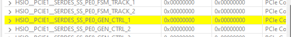
Register view#
SerDes validation#
After a SerDes configuration is created in terms of protocol/speed, lane receive and transmit, and PLL allocation, the question is whether that configuration will perform reliably under the intended type of traffic.
The validation relies on the SerDes hardware block build-in, programmable test capabilities that are used to verify the block under different conditions. The validation programs the build-in testing capabilities and then runs a series of tests.
The SerDes validation uses different scenarios to assess SerDes performance by downloading a test image to the processor’s internal RAM using the Serial Download mode. Results are sent to the SerDes tool via UART.
SerDes validation can help to assess the stability of the SerDes interface on the board in a non-OS environment.
Connection#
To connect to a board some prerequisites are necessary:
Configure the board to boot in the Serial download mode/Manufacture mode and power up the board.
Connect a UART cable from the host computer to the UART of the A-core on the board.
Connect a USB cable from the host computer to the USB port on the board that is used by the Serial download mode. A HID-compliant device or USB Input Device will be shown in the Windows Device Manager.
Note: It is highly recommended to connect the USB cable directly to the Host PC USB port and not through a USB HUB.
With the board connected to the host computer, the next step is to search for the UART ports by using COM port scan. The COM port drop-down list is populated with all the available UART ports.
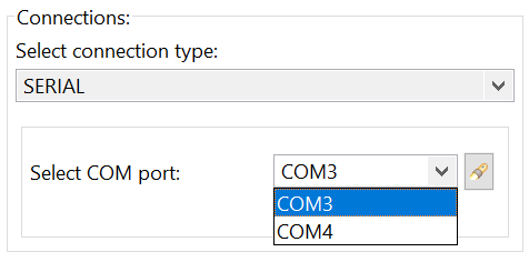
COM port drop-down list#
Choose the correct UART that is used as the A-core debug UART port.
Test scenarios#
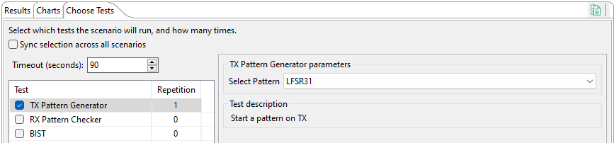
Once the SerDes configuration and board connection are set up, different Test scenarios can be executed. Each test can be customized by setting the parameters from Test options.
Depending on the test and options selected, the execution time may differ. By default, a 90-second timeout is set, to assure that in case of an issue the test finishes. To change the default value, edit the Timeout (seconds) option:
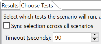
Timeout option#
To start test execution, press the Start Validation button. Check the status of the running test from the Logsconsole. By default, the log level is set to INFO. Additional log level options are available with different output in the console:
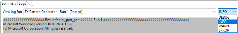
Additional log level options#
At the end of the test, the status is displayed in Results with the test summary in Summary.
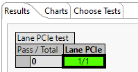
Test summary#
Each cell color can be decoded using the Legend (see the figure below)
Yellow is for Test failed
Orange is for Configuration error
Red is for Target connection error or exception in the script
Green is for Test passed
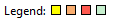
Legend#
The SerDes tool offers several test scenarios for each available lane.
TX pattern generator#
Running the TX pattern generator test drives the SerDes module to generate a specific pattern (set up by the user) on the TX side of the lane that is being verified.
TX pattern generator#
The TX pattern generator test can be used in an environment with two devices connected in a way that:
One device starts transmitting data with the TX pattern generation test.
The other device verifies the received data with the BIST test or the RX Pattern Checker in External mode.
The TX pattern generator test continues to run until the board is restarted.
RX pattern checker#
The RX pattern checker verifies the pattern received on the RX side.
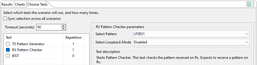
RX pattern checker#
BIST#
Build-in self-test (BIST) refers to a quick self-evaluation of a hardware block.
Running a BIST test involved the following steps:
Choose a pattern to be generated and how the traffic flows through the lane (that is Loopback mode: Disabled, Internal, External).
Choose the number of Insert Error. The BIST output must contain the same number of generated errors as the number of errors inserted. This is a quick on-the-fly method to detect if some bits were lost.
Choose the Time to wait. This represents how much traffic is generated and analyzed by the SerDes lane. The time can widely vary from seconds to days, having a direct impact on when BIST results are available.
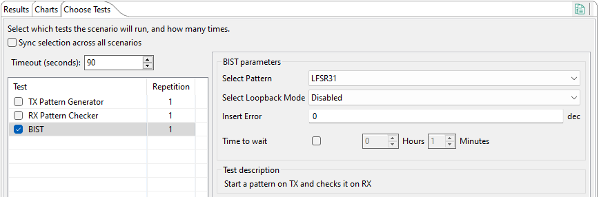
BIST test#