User Interface#
Start Development wizard#
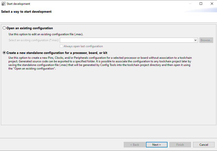
Upon starting Config Tools, you are automatically welcomed by a startup wizard. With this wizard, you can create a configuration or open an existing one.
Note: To skip the wizard on subsequent startups, select the Always open last configuration checkbox below the Open an existing configuration option. You can also perform the same action by selecting the Automatically open previously used configuration checkbox in Preferences.
Start development wizard#
Note: The content of this wizard is similar to the wizard that you open by selecting File > New in the Menu bar.
Creating, saving, and opening a configuration#
In this context, configuration stands for common tools settings stored in an MEX (Microcontrollers Export Configuration) file. This file contains settings of all available tools. The folder with the saved MEX file must contain exactly one project file to be able to parse the toolchain project.
Creating a new configuration#
You can create a configuration from the Start development wizard or by selecting File > New from the Menu bar.
If you start creating your development for any NXP board or kit, we recommended you start with example to create a configuration for a board or a kit. Such configuration contains board-specific settings. If you select a processor, the configuration will be empty.
After the new configuration is created, you can continue by importing an existing configuration from an MEX file. It is useful if you already have a configuration available or if you want to reuse a previous configuration. To import an existing configuration from an MEX file, select File > Import… > Import configuration (*.mex) from the Menu bar.
Creating a new standalone configuration#
You can create a new configuration that is not part of any toolchain project.
Creating a new configuration#
To create a standalone configuration, do the following:
In the Start development wizard select Create a new standalone configuration for processor, board, or kit. Alternatively, in the Menu bar, select File > New.
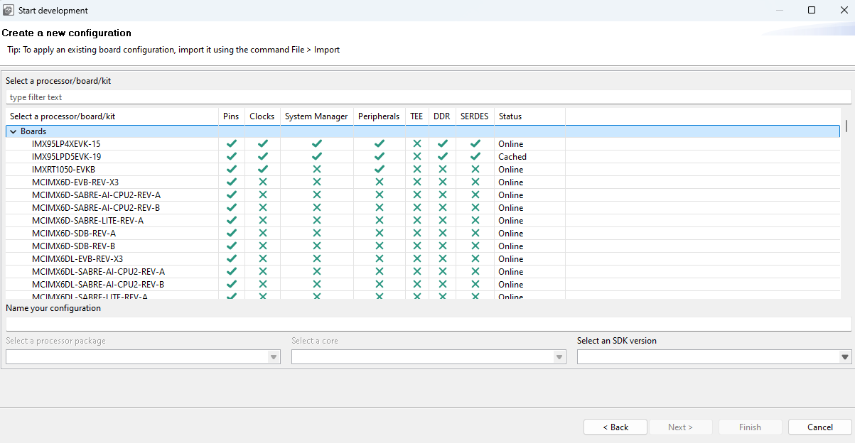
Click Next.
Select the processor, board, or kit from the list.
Note: If you are working offline, you will only see locally saved options. For more information, see the Working offline section.
Name your configuration. Optionally, you can select processor package, core, and SDK version.
Click Finish.
Saving a configuration#
To save your configuration for future use, select File > Save from the Menu bar.
To save a back-up of your configuration, do the following:
In the Menu bar, select File > Save Copy As.
In the dialog, specify the name and destination of the configuration.
Click Save.
The folder with the saved MEX file must contain exactly one project file to be able to parse the toolchain project.
Opening an existing configuration#
To open an existing configuration, do the following:
In the Start development wizard, select Open an existing configuration. Alternatively, in the Menu bar, select File > Open.
Click Browse to navigate to your configuration file.
Select the configuration file and click Open.
Optionally, select Always open last configuration to skip the Start development wizard and load the last-saved configuration by default.
User templates#
You can export and store the current configuration as a user template for later use as a reference configuration file.
Export template#
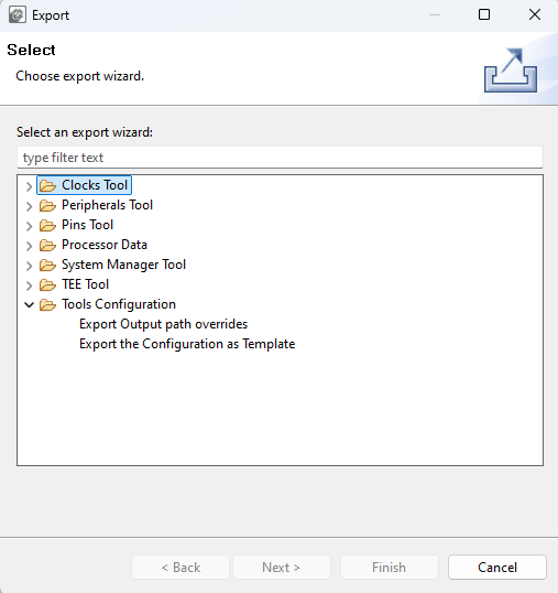
The exported template is available in the New Configuration wizard and can be used to create a configuration. You can also define custom labels for pins or identifiers prefixes for #define in generated code. You can export the configuration by selecting, in the Menu bar, File > Export > Tools Configuration > Export Configuration as Template.
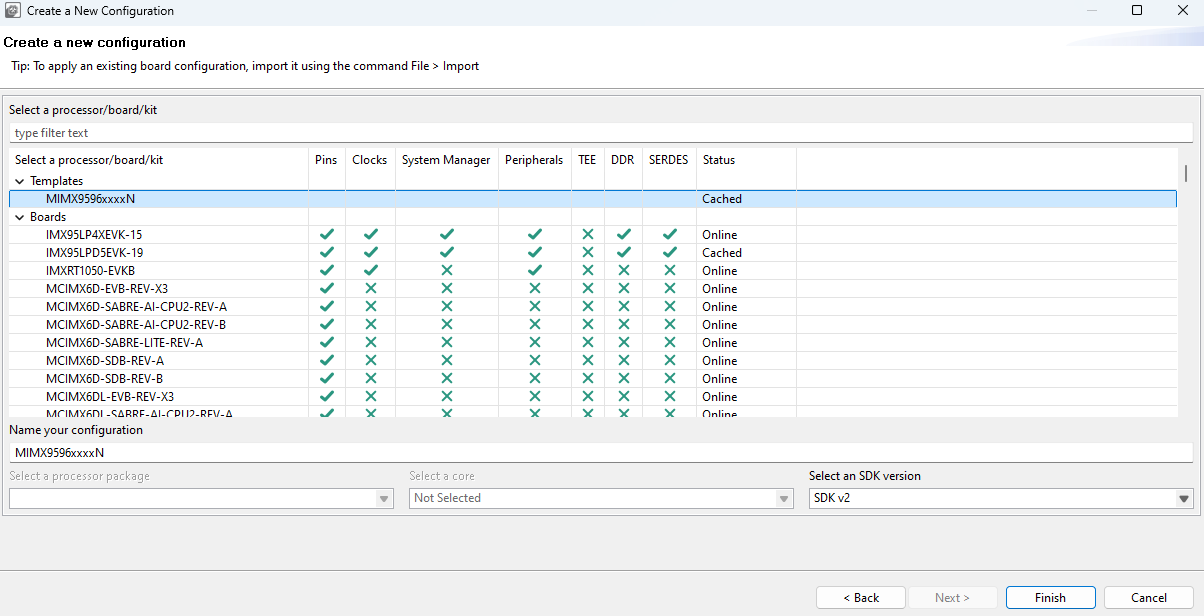
Create a new configuration from the template#
Note: The templates are stored in at the following location on your local hard disk: {$user}/.nxp/{tools_folder}/{version}/templates.
Importing sources#
You can import source code files to use as a basis for further configuration.
Note: You can import only C or DTSI files containing valid YAML configuration blocks generated by the Config Tools. The configuration is reconstructed from the YAML block and the rest of the imported file is ignored.
To import source code files, do the following:
In the Menu bar, select File > Import….
From the list, select MCUXpresso Config Tools > Import Source.
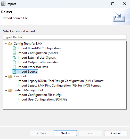
Import Source wizard#
Click Next.
On the next page, click Browse to specify the location of the source file.
Select the source file that you wish to import and click Open.
On the next page, select which functional groups to import (based on tools) by selecting the checkbox in the left column.
Define how to import the functional groups by selecting one of the two available options in the dropdown menu in the right column:
Rename – All files are merged into the current configuration. It imports all the functions only. If the imported function has the same name as an existing one, it is automatically renamed to the indexed one. For example, if
BOARD_InitPinsexists in the configuration then the imported function is renamed toBOARD_InitPins1.Overwrite – All files are merged into the current configuration. It imports all the functions only. If the imported function has the same name as an existing one, then the existing one is replaced with the imported one.
Click Finish.
Importing configuration#
To import an existing configuration from an MEX file, do the following:
In the Menu bar, select File > Import…>.
In the Import wizard, select MCUXpresso Config Tools > Import configuration (*.mex).
Click Next.
On the next page, click Browse to specify the location of the registers file.
Select the MEX file that you wish to import and click Open.
On the next page, select which functional groups to import (based on tools) by selecting the checkbox in the left column.
Define how to import the functional groups by selecting one of the two available options in the dropdown menu in the right column:
Rename – All files are merged into the current configuration. It imports all the functions only. If the imported function has the same name as an existing one, it is automatically renamed to the indexed one. For example, if
BOARD_InitPinsexists in the configuration then the imported function is renamed toBOARD_InitPins1.Overwrite – All files are merged into the current configuration. It imports all the functions only. If the imported function has the same name as an existing one, then the existing one is replaced with the imported one.
Click Finish.

Import Wizard#

Import configuration#
Importing Board/Kit Configuration#
Use import settings from default board/kit templates provided within CFG tools data for further configuration.
To import board/kit configuration, do the following:
In the Menu bar, select File > Import…>.
In the Import wizard, select Config Tools for i.MX > Import Board/Kit Configuration.
Click Next.
On the next page, select the board/kit variant from the dropdown menu.
Select which functional groups to import (based on tools) by selecting the checkbox in the left column.
Define how to import the functional groups by selecting one of the two available options in the dropdown menu in the right column:
Rename – All files are merged into the current configuration. It imports all the functions only. If the imported function has the same name as an existing one, it is automatically renamed to the indexed one. For example, if BOARD_InitPins exists in the configuration then the imported function is renamed to BOARD_InitPins1.
Overwrite – All files are merged into the current configuration. It imports all the functions only. If the imported function has the same name as an existing one, then the existing one is replaced with the imported one.
Click Finish.
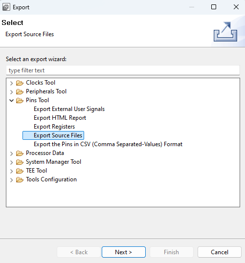
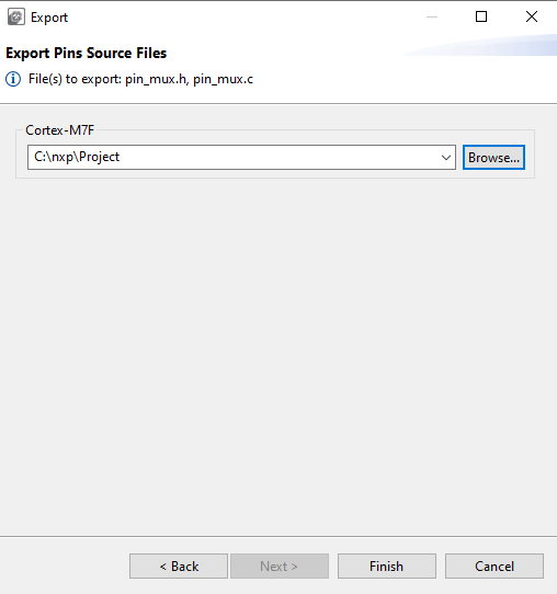
Exporting sources#
It’s possible to export the generated source using the Export wizard.
To launch the Export wizard:
Toolbar#
The toolbar is on the top of the window and includes buttons/menus of frequently used actions common to all tools. See the following sections for more information.
Item |
Description |
|---|---|
Config Tools Overview |
Open the Overview dialog with information about currently used tools. |
Show Problems View |
Open the Problems view. |
Update Code |
Open the update dialog allowing you to update generated peripheral initialization code directly within specified toolchain project. |
Generate Code |
Regenerate source code when “Enable Code Preview” preference is disabled. |
Functional group selection |
Select functional group. Functional group in the Peripherals tool represents a group of peripherals that are initialized as a group. The tool generates a C function for each function group that contains the initialization code. |
Call from default initialization |
Set the current functional group to be initialized by the default initialization function. |
Functional group properties |
Open the Functional group properties dialog to modify name and other properties of the function group. |
Tool selection |
Display icons of individual tools. Use them to switch between tools. |
Undo/Redo |
Undo/Redo last action. |
In addition, the toolbar may contain additional items depending on the selected tool. See the chapters dedicated to individual tools for more information.
Config tools overview#
The Config Tools Overview provides you with general information about your currently active configuration, hardware, and project. It also provides a quick overview of the used/active and unused/inactive tools, generated code, and functional groups. By default, the Config Tools Overview icon is on the left side of the toolbar.
Config Tools Overview contains several items.
Item |
Description |
|---|---|
Configuration – General Info |
Displays the name of and the path to the MEX file of the current configuration. Click the link to open the folder containing the MEX file. To import additional settings, click the Import additional settings into current configuration button. |
Configuration – HW Info |
Displays the processor, part number, core, and SDK-version information of the current configuration. |
Project |
Displays toolchain project information. |
Pins/Clocks/Peripherals/DDR/SERDES/PBL/TEE |
Displays basic information about Pins, Clocks, Peripherals, DDR, SERDES, PBL, TEE tools. |
To enable/disable the tools, click the toggle button. You can navigate to the tools by clicking their icons. Following information about the tools is also available:
Item |
Description |
|---|---|
Generated code |
Contains the list of source-code files. Click the links to open the files in the Code Preview view. |
Functional groups |
Contains the list of the currently active functional groups. To select the groups in the Functional groups tab in the toolbar, select the relevant links. |
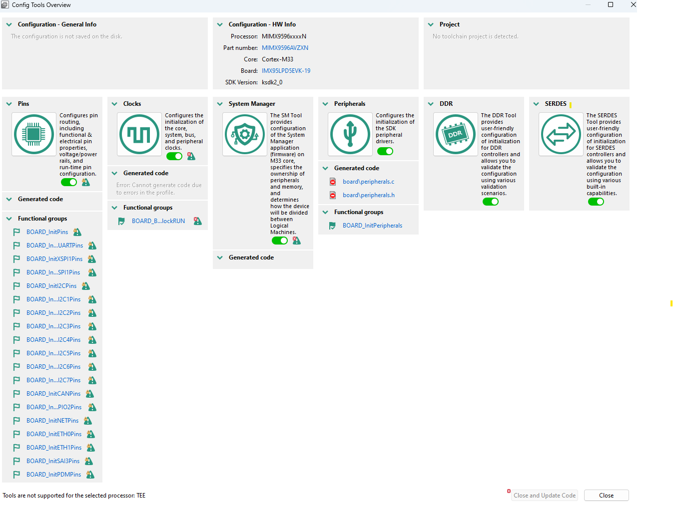
Config Tools Overview#
Note: Unsupported tools are not displayed in the overview.
Update code#
To update the project without opening the Update Files dialog, deselect the Always show details before Update Code checkbox.
To access the Update Code dialog from the Update Code dropdown menu, select Open Update Code Dialog.
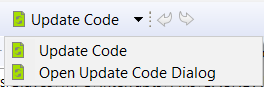
Update Code dropdown menu#
Note: The generated code is always overwritten.
The Update Code action is enabled under following conditions:
If the MEX configuration is saved in a toolchain project, the processor selected in the tool matches with processor selected in the toolchain project
Core is selected (for multicore processors)
Functional groups#
Every Pins configuration can contain several functional groups.
These groups represent functions which will be generated into source code. Use the dropdown menu to switch between functional groups and configure them.

Functional groups#
You can use two additional buttons to further configure functional groups:
Icon |
Description |
|---|---|
|
Toggle “Called from default initialization function” feature (in source code) |
|
Opens the Functional group properties window |


Note: Red/orange background indicates errors/warnings in the configuration.
Functional group properties#
In the Functional Group Properties window, you can configure several options for functions and code generation. Each setting is applicable for the selected function. You can specify generated function name, select core (for multicore processors only) that is affecting the generated source code, or write function description (this description is generated in the C file). You can also add, copy, and remove functional groups as needed.
Aside from name and description, you can choose to set parameters for selected functional groups.
Functional group properties are specific for individual Config Tools:
The Pins tool:
Set custom #define prefix- If this property is set, the specific custom prefix is used for macros generated into the
pin_mux.h.Otherwise the name of the functional group is used as the prefix.Prefix - The custom prefix string. If it is empty, no prefix is used.
Clocks gate enable - If this property is enabled, the clock gate is enabled in the generated code. The clock gate is needed for access to the peripherals, so have it enabled elsewhere.
Core(for multicore processors only) - Selects the core that is used for executing this function.
Full pins initialization - If this property is set, all features of the pins are fully initialized in the generated function even if matches the after-reset state of the processor. If it is not set, values “Not specified” or “No init” can be selected.
De-initialization function - If this feature is set, an additional function that sets all pins and peripheral signals in this functional group to their after-reset state is generated. The new function has a suffix
_deinitby default.Set custom de-initialization function name - Allows specifying a user-defined name of the de-initialization function.
Clocks tool:
Set custom #define prefix - If this property is set, the custom prefix is used for macros define in
clock_config.hOtherwise the name of the functional group is used as the prefix.Prefix - The custom prefix string. If it is empty, no prefix is used.
Other settings - The processor-specific settings are specific for each processor. See the tooltips for details.
Peripherals tool:
Prefix - It is used for identifiers, constants, and functions related to the functional group that is used in generated code. If it is not specified, no prefix is used.
TEE tool:
Set custom #define prefix - If this property is checked, the custom prefix is used for macros define in generate code. Otherwise the name of the functional group is used as the prefix.
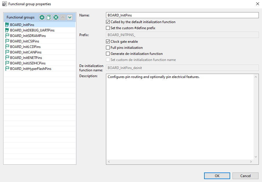
Functional group properties for the Pins tool#
Undo/Redo actions#
You can reverse your actions by using Undo/Redo buttons available in the Toolbar. You can also perform these actions from the Edit menu in the Menu bar.
Icon |
Description |
|---|---|
|
Cancels the previous action |
|
Cancels the previous undo action |
Preferences#
To configure preferences in the Preferences dialog, select Edit>Preferences from the Menu bar.
Note: You can restore settings to default by selecting Restore Defaults in the lower right corner of the dialog.
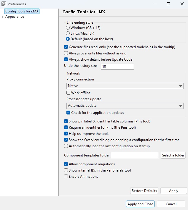
Preferences#
Several settings are available.
Item |
Description |
|---|---|
Line ending style |
Select between Windows (CR + LF), (LF), or Default (based on host). |
Always overwrite files without asking |
Update existing files automatically, without prompting. |
Always show details before Update Code |
Review changes before the project is updated. |
Undo history size |
Enter the maximum number of steps that can be undone. Enter 0 to disable. |
Proxy connection |
- Direct – Connect directly and avoid a proxy connection. |
Work Offline |
Disable both the connection to NXP cloud and the download of processor/board/kit data. |
Processor data update |
Select from the following options:- Auto Update – Update the processor data automatically. |
Check for application updates |
Check for application updates on a weekly basis |
Show pin label & identifier table columns (Pins Tool) |
Select to show the pin label and the label identifier in the relevant views. |
Require an identifier for Pins (Pins Tool) |
Controls generation of pins “Identifier” related warnings. With this preference enabled, warnings will be generated for bidirectional signals that have no Identifier set. |
Help us improve the tool |
Send device-configuration and tool-use information to NXP. Sending this information to NXP helps fix issues and improve the tools |
Show Overview window on opening configuration for the first time |
Open the Overview dialog on opening configuration for the first time. |
Automatically load last configuration on startup |
Avoid the startup window and load the last used configuration instead. |
Enable animations |
Enables animations in the user interface, such as smoother scrolling or opening a drop-down menu. |
Configuration preferences#
The configuration preferences are general preferences stored within the configuration storage file (MEX).
To configure the preferences related to the configuration, select Edit > Configuration Preferences from the main menu.
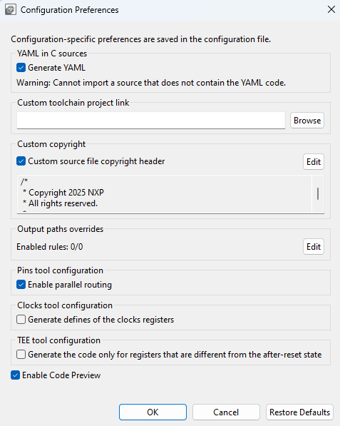
Configuration preferences#
The following preferences are available:
Item |
Description |
|---|---|
Generate YAML |
Select to generate YAML into C source files. |
Custom toolchain project link |
Select to set the path to the toolchain project folder, otherwise the default path in the same folder as the configuration is used. An absolute path or a relative path to a saved configuration (MEX) can be used. Only for standalone Config Tools. |
Custom source file copyright header |
Select to add a custom copyright header to generated source files that do not already contain copyright. |
Output path overrides |
Rules that are used to override the path of the output files are generated by the tools. They are applied in the Update code and Exports commands. A special dialog allows editing. |
Generate code only for registers that are different from the after-reset state |
Select to generate code for registers that are different from the after-reset state. |
Enable Code Preview |
Controls how the code is generated. When this preference is enabled, code generation is performed automatically after every change in the configuration and the Code Preview is updated accordingly. When this preference is disabled, code generation is stopped, warning message is displayed in Code Preview window, and the action can be manually triggered by using one of the available options: - By pressing the “generate code” link highlighted in the warning message from the Code Preview window. |
Warning: When the source does not contain YAML code, it cannot be imported.
Problems view#
The Problems view displays issues in individual tools and in the inter-dependencies between the tools.
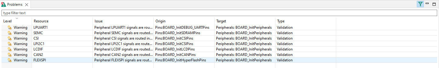
Problems view#
To open the Problems view, click the Show Problems view button in the Toolbar, or select Views > Problems from the Menu bar.
The Problems table contains the following information:
Item |
Description |
|---|---|
Level |
Severity of the problem: Information, Warning, or Error. |
Resource |
Resource related to the problem, such as signal name, the clock signal. |
Issue |
Description of the problem. |
Origin |
Information on the dependency source. |
Target |
Tool that handles the dependency and its resolution. |
Type |
Type of the problem. It is either the validation checking dependencies between tools, or a single tool issue. |
Every issue comes with a context menu accessible by right-clicking the table row. Use this menu to access information about the problem or to apply a quick fix where applicable. You can also copy the rows for later use by right-clicking the row and selecting Copy or by using the Ctrl+C shortcut. You can use the Ctrl+left-click shortcut to add additional rows to the selection.
Note: Quick fix is only available for problems highlighted with the “light bulb” icon.
Filter buttons are available on the right side of the Problems view ribbon.
Button |
Description |
|---|---|
|
Filters messages in the Problems view. If selected, only problems for the active tool are displayed. See Configuration preferences section for details. |

Registers view#
The Registers view lists the registers handled by the tool models. You can see the state of the processor registers that correspond to the current configuration settings and also the state that is in the registers by default after the reset. The values of the registers are displayed in the hexadecimal and binary form. If the value of the register (or bit) is not defined, an interrogation mark “?” is displayed instead of the value.
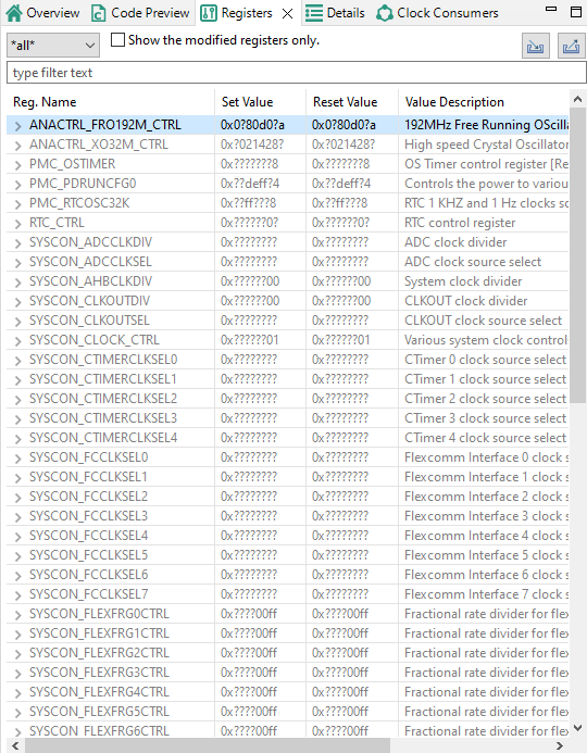
Registers view#
The Registers view contains several items.
Item |
Description |
|---|---|
Peripheral filter drop-down list |
List the registers only for the selected peripheral. Select all to list registers for all the peripherals. |
Show modified registers only checkbox |
Hide the registers that are left in their after-reset state or are not configured. |
Text filter |
Filter content by text. |
Import/Export registers |
Import/Export registers from/to CSV (Import is available only for the Clocks tool) |
The following table lists the color highlighting styles used in the Registers view.
Color |
Description |
|---|---|
Yellow background |
Indicates that the bitfield has been affected by the last change made in the tool. |
Gray text color |
Indicates that the bitfield is not edited and the value is the after-reset value. |
Black text |
Indicates the bit-fields that the tool modifies. |
Note: When the Peripherals tool is active and register initialization components are used, the user can perform manual changes to some of the displayed values.
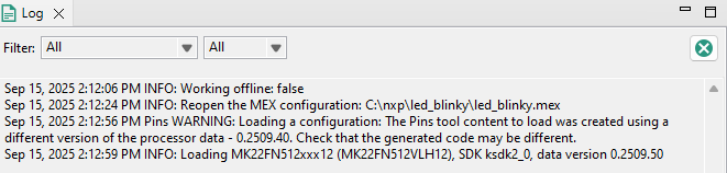
Log view#
The Log view shows user-specific information about Tools operations. The Log view can show up to 100 records across all tools in chronological order.
Each log entry consists of a timestamp, the name of the tool responsible for the entry, severity level, and the actual message. If no tool name is specified, the entry was triggered by shared functionality.
You can filter the content of the Log view using the combo boxes to display only specific tool and/or severity level information. Filters in different tools can be set independently.
Buffered log records are cleared using the clear button. It affects Log views across all tools.
Log view#