Trusted Execution Environment Tool#
In the Trusted Execution Environment, or TEE tool, you can configure security policies of memory areas, bus masters, and peripherals, in order to isolate and safeguard sensitive areas of your application.
You can set security policies of different parts of your application in the Security Access Configuration and its subviews, and review these policies in the Memory Attribution Map, Access Overview and Domains Overview views. Use the User Memory Regions view to create a convenient overview of memory regions and their security levels.
You can also view registers handled by the TEE tool in the Registers view, and inspect the code in the Code Preview tool.
Note: In order for your configuration to come into effect, make sure you have enabled the relevant enable secure check option in the Miscellaneous subview of the Security Access Configuration view.
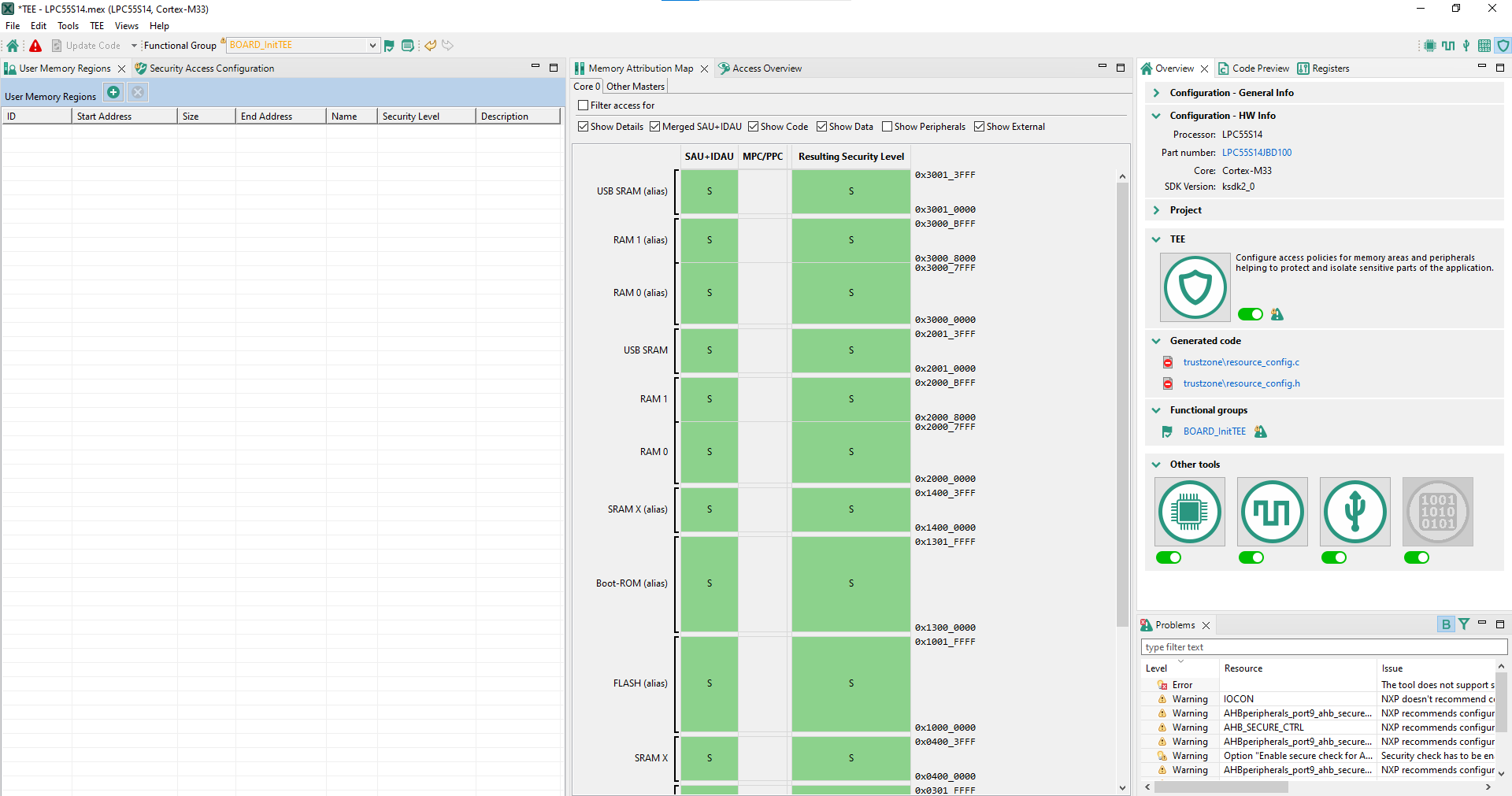
TEE tool user interface (SAU+IDAU)#
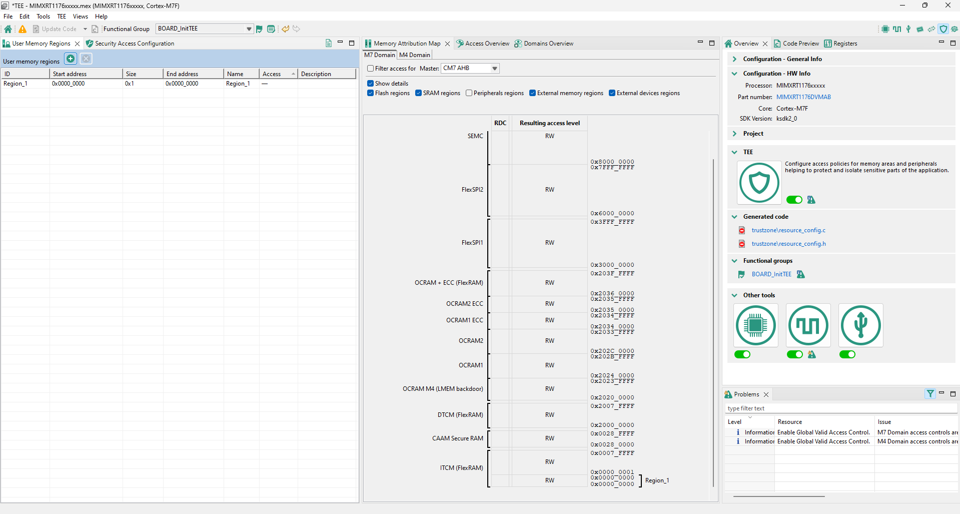
TEE tool user interface (RDC)#
AHBSC with security extension-enabled devices#
The features and appearance of the TEE tool are based on the security model of the loaded device.
This section describes the features and appearance of the tool for devices with a security extensionTrustZone-M with AHBSC.
Currently, the following devices of this type are supported:
LPC55Sxx
LPC55S69, LPC55S66
LPC55S16, LPC55S14, LPC55S36
LPC55S06, LPC55S04
RT6xx, RT5xx, RT7xx
MIMXRT685S, MIMXRT633S
MIMXRT595S, MIMXRT555S, MIMXRT533S1
MIMXRT735, MIMXRT758, MIMXRT798
MCXN
MCXN546, MCXN547, MCXN946, MCXN947, MCXN236, MCXN235
User Memory Regions view#
In the User Memory Regions view, you can create and maintain a high-level configuration of memory regions and their security levels. You can create the regions, name them, specify their address, size, security level, and provide them with a description. You can then fix any errors in the settings with the help of the Problems view.
Create a new memory region by clicking the Add new memory region button in the view’s header.
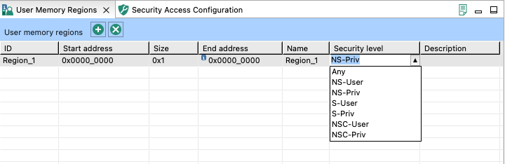
Enter/change the memory region’s parameters by clicking the row’s cells. In the Security Level column, you have these options to choose from:
NS-User - Non-secure user
NS-Priv - Non-secure privileged
S-User - Secure user
S-Priv - Secure privileged
NSC-User - Non-secure callable user
NSC-Priv - Non-secure callable privileged
Any
Errors in configuration are highlighted by a red icon in the relevant cell. In the case the issue is easily fixed, you can right-click the cell to display a dropdown list of offered solutions.
Remove the memory region by selecting the table row and clicking the Remove selected memory region(s) button in the view’s header.
User Memory Regions#
Security Access Configuration view#
In the Security Access Configuration view, you can configure your application’s security policies in a number of ways. See the following sections for more details.
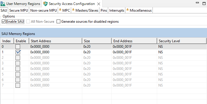
SAU#
In the SAU subview, you can enable and configure SAU (Security attribution unit).
When enabled, you can set up SAU memory regions, specify their start and size or end address, and specify their access level. SAU automatically sets the entire memory space to a Secure access level when disabled. When enabled, SAU deems every uncovered (that is, unconfigured) memory region as Secure, so only NS or NSC can be selected for a covered (configured) memory region.
You can choose between two access levels:
NS - Non-secure
NSC - Non-secure callable
Alternatively, you can set all the SAU memory regions to non-secure access level by selecting the All Non-Secure.
Note: This option is only available when SAU is disabled.
You can also decide to generate code even for disabled memory regions by selecting the option Generate sources for disabled regions.
SAU/IDAU#
Interrupts#
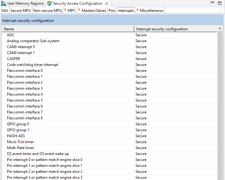
In the Interrupts subview, you can set security designation for device’s peripheral interrupts. In case if the processor contains more than a single core or processing unit, additional Handling by Core tables might appear. In these tables, you can specify if the interrupts coming from the peripheral can be handled by the core or processing unit.
All interrupts are set to Secure by default. If you want to change the interrupt source’s security designation, left-click the Secure cell of the interrupt and choose from the dropdown menu. Alternatively, right-click the interrupt’s Name cell and choose the security designation from the context menu. To select multiple entries, use the Ctrl+Left-click shortcut, then right-click the selected area for the context menu. Alternatively, you can use Shift+Up/Down after selecting the row to expand the selection.
Interrupts#
Secure/Non-secure MPU#
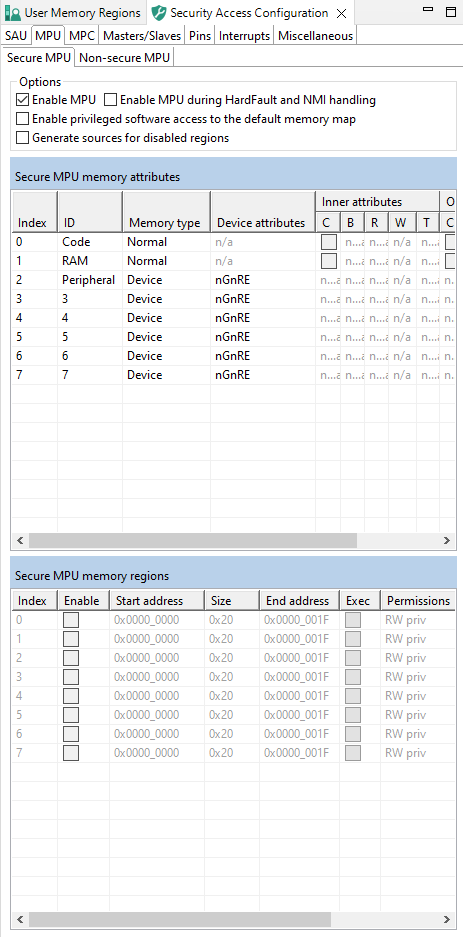
In the Secure MPU and Non-secure MPU sub-views, you can enable and configure MPU (Memory Protection Unit). You can create regions, specify their address, size, and other parameters. Use the Secure MPU sub-view for the configuration of the secure, and Non-secure MPU for the configuration of the non-secure security level.
MPU#
MPU is disabled by default and must be enabled by selecting the Enable MPU option.
Note: Not every device supports MPU.
Use the MPU Memory Attributes table to name and configure MPU memory attribute sets. Click the cells of the Memory Type and Device Attributes columns to display the available choices.
Use the MPU Memory Regions table to enable and configure MPU memory regions.
Enable the region.
Specify the Address.
Specify either the Size or the End Address.
Set the Exec option if you want the region to be able to run code.
Set the Permissions (Read Only or Read/Write).
Set the Privileges.
Note: Privileged access can be set by default for all memory regions not handled by MPU by selecting the Enable privileged software access to the default memory map option.
Set the Shareability, or the caching options.
Allocate one of the sets from the MPU Memory Attributes table in Mem.Attr.. Sets can be allocated to more than one region.
MPC#
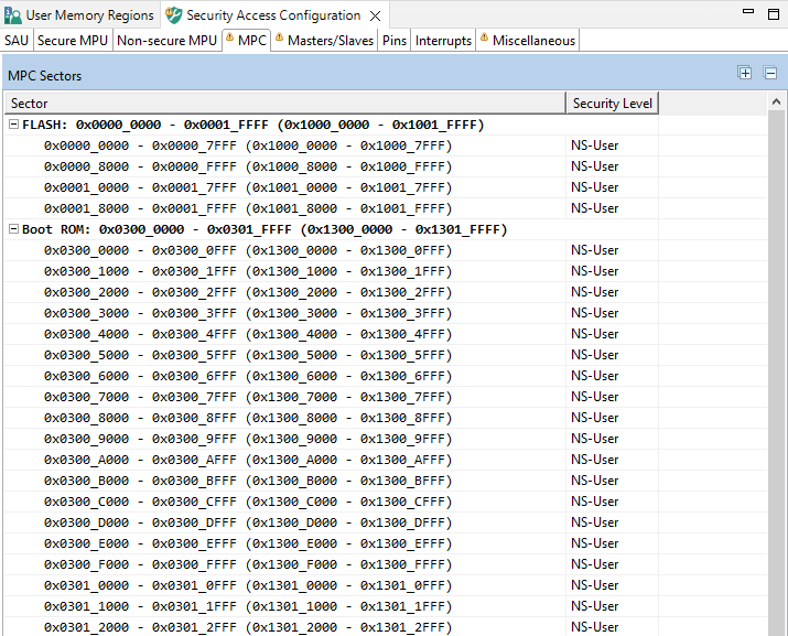
In the MPC (Memory Protection Checker) subview, you can set security policies on entire memory sectors as defined by physical addresses.
Set the memory sector security level by left-clicking the relevant cell in the Security level column and choosing from the dropdown list. Alternatively, you can right-click the relevant cell in the Sector column and choose the security level from the context menu. To select multiple entries, use the Ctrl+Left-click shortcut, then right-click the selected area for the context menu.
You have four security levels to choose from, in ascending order of security:
NS-User - Non-secure user
NS-Priv - Non-secure privileged
S-User - Secure user
S-Priv - Secure privileged
MPC#
Masters/Slaves#
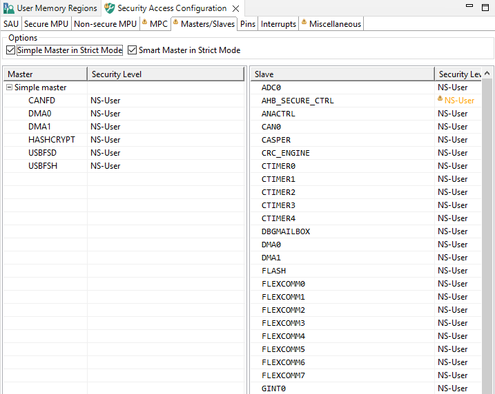
In the Masters/Slaves subview, you can configure security levels for bus masters and slaves.
Set the bus master/slave security level by left-clicking the relevant cell in the Security level column and choosing from the dropdown list. Alternatively, you can right-click the relevant cell in the Master and Slave column and choose from the security level from the context menu. To select multiple entries, use the Ctrl+Left-click shortcut, then right-click the selected area for the context menu.
You have four security levels to choose from, in ascending order of security:
NS-User - Non-secure user
NS-Priv - Non-secure privileged
S-User - Secure user
S-Priv - Secure privileged
You can further specify the interrelation between master and slave security levels by selecting the following options:
Simple Master in Strict Mode - Select to allow simple bus master to read and write on same level only. De-select to allow to read and write on same and lower level.
Smart Master in Strict Mode - Select to allow smart bus master to execute, read, and write to memory at same level only. De-select to allow to execute on same level only, read and write on same and lower level.
Note: Instruction-type bus master security level must be equal to bus slave security level. Data and others security level must be equal or higher than bus slave security level.
Masters/Slaves#
Pins#
In the Pins subview, you can specify if the reading GPIO state is allowed or denied.
All pins’ reading GPIO state is set to Allow by default. If you want to change the pins reading GPIO state, left-click the Reading GPIO state cell of the pin and choose from the dropdown menu. Alternatively, right-click the pin’s Name cell and choose the reading GPIO state from the context menu. To select multiple entries, use the Ctrl+Left-click shortcut, then right-click the selected area for the context menu. Alternatively, you can use Shift+Up/Down after selecting the row to expand the selection.

Pins tab on LPC55S69#
Global Access Templates#
Local access templates#
Miscellaneous#
In the Miscellaneous subview, you can set various configuration options. The list of these options depends on processor data, and varies greatly. All the options influence your register settings, and can be inspected in the Register view. Only some of the options directly influence configuration that you have made in the Security Access Configuration view. Point your cursor over individual options to display a tooltip explaining the function of each option.
A togglable checkbox enables or disables the code generation for the entire group. When the group is disabled, the code generation for that group is suspended, the generation options within it cannot be edited, and all option configurations revert to their default values (either reset values or default values).
Miscellaneous#
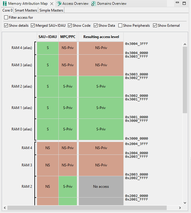
Memory attribution map#
In the Memory attribution map, you can view security levels set for memory regions. This view is read-only.
Core 0#
In the Core 0 subview, you can review security levels set for Core 0 to the code, data, and peripherals memory regions. The table is read-only.
The Access by Master table displays MSW or SAU+IDAU, MPC (Memory Protection Checker) security level, and Resulting access level status of listed code, data, and peripherals memory regions, alongside their physical addresses.
To set the display options, do the following:
Click the Filter access for checkbox to enable filtering options.
Select the master security access that you want to review by choosing from the Master dropdown menu.
Optionally, set the security state and execution privilege check-boxes when master allows more security levels. This setting has no effect on the configuration.
Optionally, customize the output by de-selecting the Show details and Merged SAU+IDAU options.
Optionally, filter displayed memory regions in the Filter area.
Point your cursor over the color-coded cells to display a tooltip with information about the security level combination.
Double-click the cell to open the pertinent settings in Security Access Configuration.
Core 0#
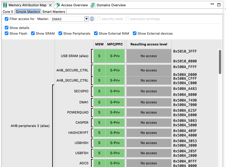
Simple and Smart masters#
In the Simple Masters and Smart Masters subviews, you can review security attributes of memory in relation to access rights by simple/smart masters. The table is read-only.
To set the display options, do the following:
Click the Filter access for checkbox to enable filtering options.
Select the master type security access that you want to review by choosing from the Master dropdown menu.
Optionally, customize the output by de-selecting the Show Details, Show Code, Show Data, Show Peripherals, and This Domain Only options.
Optionally, filter displayed memory regions in the Filter area.
Point your cursor over the color-coded fields to display a tooltip with information about the security level combination.
Double-click the cell to open the pertinent settings in Security Access Configuration.
Simple/Smart masters#
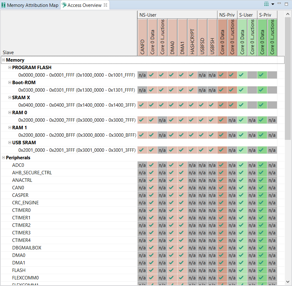
Access Overview#
In Access Overview, you can review security policies you have set in Security Access Configuration view.
The vertical axis displays all masters, divided into color-coded groups by their security settings.
The horizontal axis displays memory ranges and slave buses/peripherals.
Point your cursor at an entry to display a tooltip with information about the entry.
You can group the displayed information by security or by masters by using the button on the right-hand side of the toolbar.
Access Overview#
Code generation#
If the settings are correct and no error is reported, the code generation engine regenerates the source code. You can view the resulting code the Code Preview view of the Trusted Execution Environment tool.
Code Preview automatically highlights differences between the current and immediately preceding iteration of the code. You can choose between two modes of highlighting by clicking the Set viewing style for source differences. You can also disable highlighting altogether from the same dropdown menu. Such features as Copy, Search, Zoom-in, Zoom-out, and Export source are available in the Code Preview view. The search can also be invoked by CTRL+F or from the context menu.
Some AHBSC or TRDC with security extension-enabled devices support ROM preset as well as C code. You can choose to have the code generated in the ROM preset by selecting the option in the Miscellaneous subview.
RDC-enabled devices#
The features and appearance of the TEE tool are based on the security model of the loaded device.
This section describes the features and appearance of the tool devices enabled with RDC (Resource Domain Controller), XRDC2 (eXtended Resource Controller 2), and TrustZone-M with TRDC.
Currently, following devices of this type are supported:
RT1170
Dual core (Cortex-M7 + Cortex-M4): MIMXRT1176, MIMXRT1175, MIMXRT1173
Single core only (Cortex-M7): MIMXRT1172, MIMXRT1171
Kinetis W
KW45B41Z
KW45B410
KW47B42Z
KW47B420
i.MX RT
MIMXRT1181
MIMXRT1182
MIMXRT1187
MIMXRT1189
MCXW
MCXW716A
MCXW716C
i.MX 91
MIMX930x
MIMX931x
MIMX933x
MIMX935x
User Memory Regions view#
In the User Memory Regions view, you can create and maintain a high-level configuration of memory regions and their access templates. You can create the regions, name them, specify their address, size, security level, and provide them with a description. You can then fix any errors in the settings with the help of the Problems view.
User Memory Regions#
Create a new memory region by clicking the Add new memory region button in the view’s header.
Enter/change the memory region’s parameters by clicking the row’s cells.
Modify the access policy of memory regions by clicking the cell in the Access column. This action opens the Access templates dialog.
Errors in configuration are highlighted by a red icon in the relevant cell. In the case the issue is easily fixed, you can right-click the cell to display a dropdown list of offered solutions.
Remove the memory region by selecting the table row and clicking the Remove selected memory region(s) button in the view’s header.
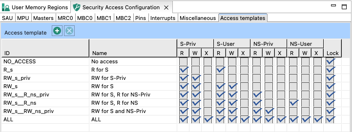
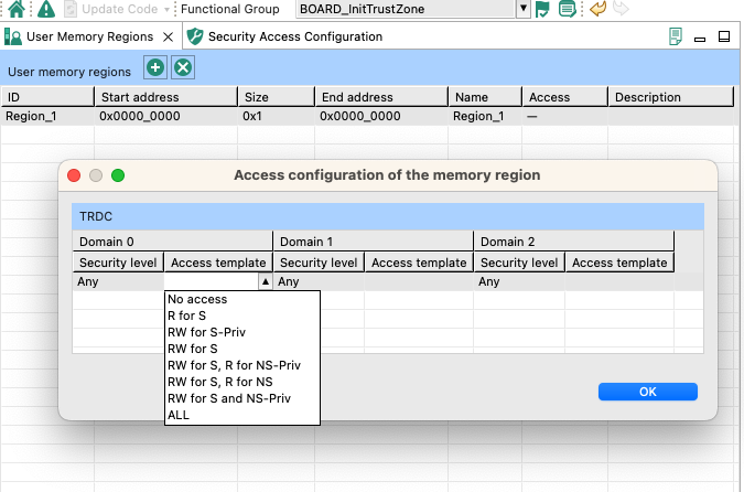
Access templates#
In the Access templates dialog, you can modify access templates for device domains. The dialog displays the device RDC domains, as well as all user-created XRDC2 domains.
Note: Make sure to first specify the number of domains in the M4 Domain/M7 Domain > Domains.
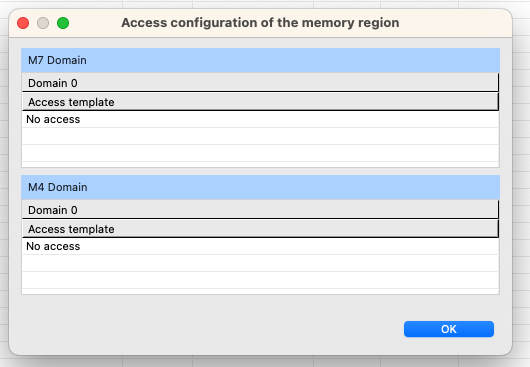
Access template#
Select access template by clicking the topmost cell of domain column to open a dropdown list containing all options.
Once you have selected access templates for all domains, click OK to return to the User Memory Regions view.
Security Access Configuration view#
In the Security Access Configuration view, you can configure your application’s security policies in a number of ways. See the following sections for more details.
RDC#
In the RDC subview, you can assign masters to domains and specify access rules for slaves for each domain.
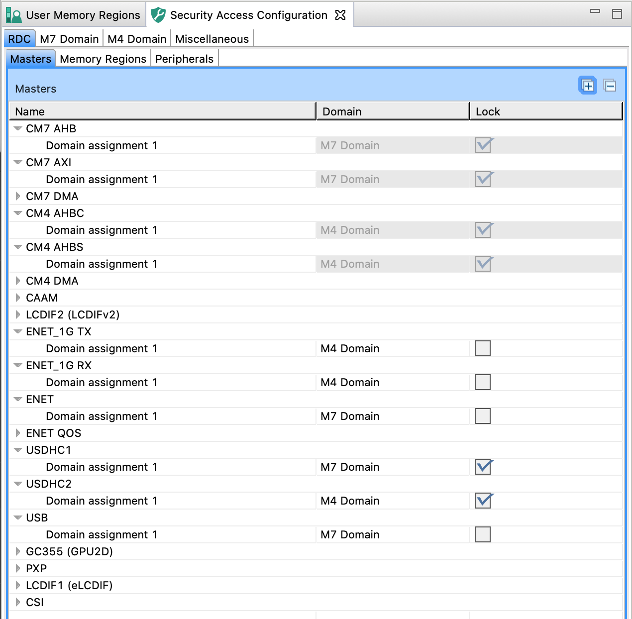
RDC Masters#
In the RDC Masters subview, you can view available bus masters, allocate them to available domains (cores), and lock/unlock the allocation.
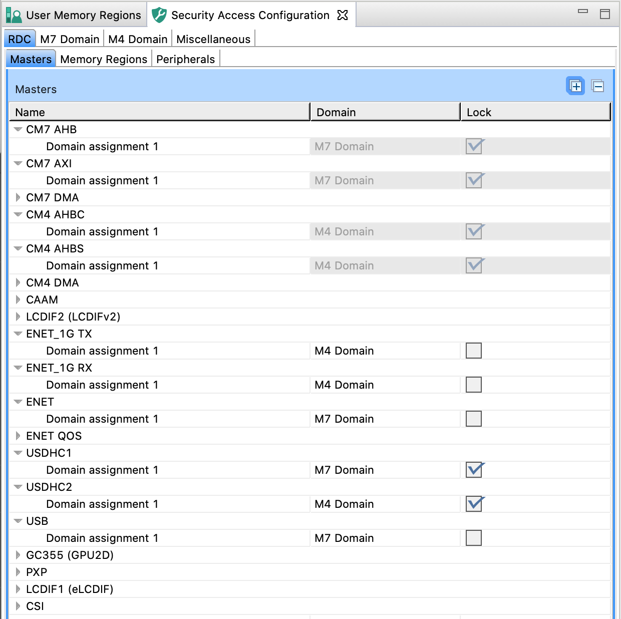
RDC Masters#
Allocate a master to a domain by clicking the cell in the Domain column in the Masters table and selecting the domain from the dropdown list.
Select the Lock checkbox to prevent further register modifications.
Alternatively, you can select the options by right-clicking the master and using the dropdown list.
Note: Some masters are allocated to specific domains by default and cannot be reallocated.
Memory Regions#
In the Memory Regions subview, you can view, enable/disable, and configure the MRC (Memory Region Controller) bus slaves and their domain access.
Memory Region Controller implements the access controls for slave memories based on the pre-programmed Memory Region Descriptor registers.
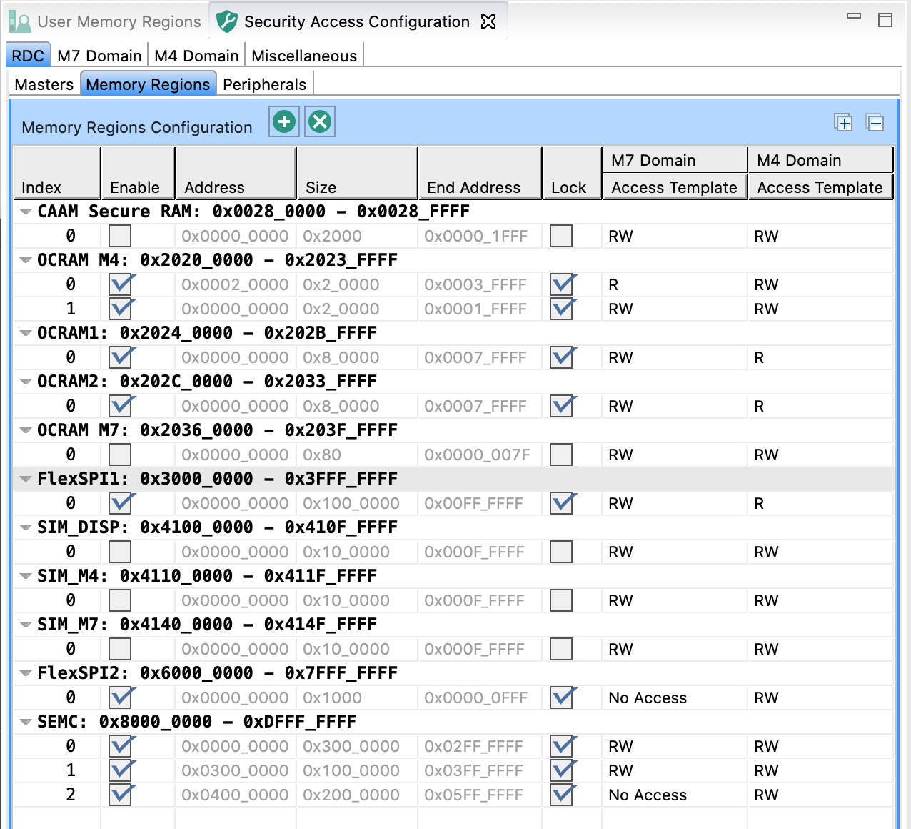
Memory Regions#
Use the Memory Regions Configuration table to enable and configure MRC slaves:
Enable the region.
Specify the Address.
Specify either the Size or the End Address.
Optional: Lock the settings to prevent further register modifications.
Set the Access Template for available domains.
Alternatively, you can select the options by right-clicking the master and using the dropdown list.
Peripherals#
In the Peripherals subview, you can view and configure the PDAP (Peripheral Domain Access Permissions) for peripherals.
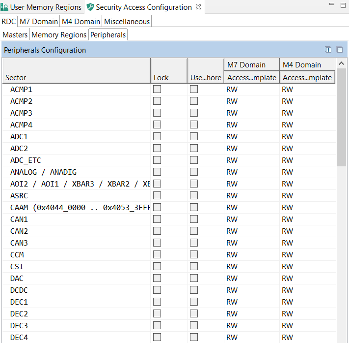
Peripherals#
Use the Peripherals Configuration table to enable and configure PDAP:
Optional: Lock the settings to prevent further register entries.
Select Use semaphore to enable the semaphore function for the peripheral.
Note: When enabled, the master cannot access this peripheral until obtaining a semaphore. During the time that the domain has the semaphore in possession, its bus masters have exclusive access to the peripheral.
Set the Access Template for available domains.
XRDC2 Domains view#
In the M7/M4 Domain subviews, you can view and configure security policies of the XRDC2(eXtended Resource Domain Controller 2) domains. Each CPU can contain up to 16 domains.
MPU#
In the MPU subview, you can enable and configure MPU (Memory Protection Unit). You can create regions, specify their address, size, and other parameters.
The MPU enforces privilege rules, separates processes, and enforces access rules to memory, and supports the standard ARMv7 Protected Memory System Architecture model.
MPU is disabled by default and must be enabled by selecting the Enable MPU option.
Note: Not every device supports MPU.
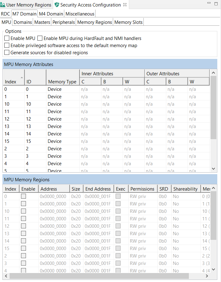
MPU#
Use the MPU Memory Attributes table to name and configure MPU memory attribute sets. Click the cells of the Memory Type and Inner/Outer Attributes columns to display the available options.
Use the MPU Memory Regions table to enable and configure MPU memory regions.
Enable the region.
Specify the Address.
Specify either the Size or the End Address.
Set the Exec option if you want the region to be able to run code.
Set the Permissions.
Set the SRD (Sub Region Disable) bits.
Set the Shareability, or the caching options.
Domains#
In the Domains subview, you can view, add/remove, and rename XRDC2 domains. Each CPU supports up to 16 XRDC2 domains.
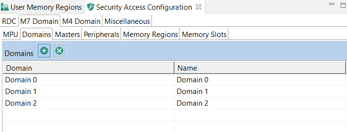
Domains#
Add a new domain by clicking the Add new domain button.
Rename the domain by entering a new name in the Name column.
Remove a domain by clicking the Remove last domain button.
Masters#
In the Masters subview, you can add/remove, view, configure XRDC2 domain assignments to available RDC masters.
Master Domain Assignment Controller (MDAC) is responsible for the generation of the DID, nonsecure and privileged attributes for every system bus transaction in the device based on pre-programmed Master Domain Assignment (MDA) registers.
Masters#
To add a new domain assignment:
Click the Add new domain assignment for the selected master button.
Select the Enable checkbox.
Enter the Match Input value.
Note: The match field specifies the reference value for the comparison with the MDAC match input. The match field width varies by MDAC instance from 0 to 16 bits. Unimplemented bits are read as 0. A size of 0 bits generates a hit on all comparisons.
Enter the Mask Input value.
Note: The mask field specifies which bits are valid for the match comparison. Only bit positions in which the mask value is zero are compared. The mask field width is the same as the mask field which varies by MDAC instance from 0 to 16 bits. A mask value of all ones generates a hit on all comparisons.
Select the XRDC2 domain assignment from the dropdown list in the Domain column.
Select the security access type from the dropdown list in the Secure column.
Select the privileged access type from the dropdown list in the Privileged column.
Optional: select the Lock checkbox to prevent further register modifications.
Peripherals#
In the Peripherals subview, you can view the access templates for PAC (Peripheral Access Controller) and configure access for all peripherals managed by PAC on the selected RDC domain.
The Peripheral Access Controller submodule performs access control for a set of peripherals connected to a peripheral bus bridge or integrated into a peripheral subsystem.
The Access Template table displays the ID and name of all access templates available for the PAC on the selected device. The information is data driven and display-only.
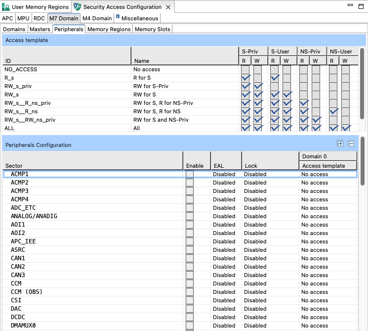
Peripherals#
Use the Peripherals Configuration table to configure access for a peripheral:
Select the Enable checkbox.
Set the Lock to the desired state.
Set the Access Template for all listed domains.
Alternatively, you can select the options by right-clicking the master and using the dropdown list.
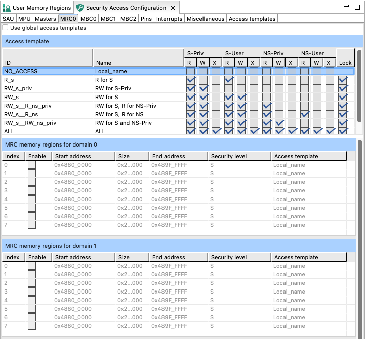
Memory Regions#
In the Memory Regions subview, you can view the access templates for MRC (Memory Region Controller) and configure access for all non-peripheral memory spaces managed by MRC on the selected RDC domain.
The Memory Region Controller (MRC) provides domain-based, hardware access control for all system bus references targeted at non-peripheral memory spaces.
The Access Template table displays the ID and name of all access templates available for the MRC on the selected device. The information is data driven and display-only.
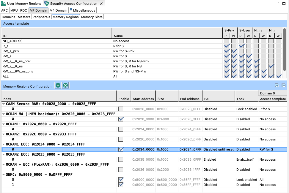
Memory Regions#
Use the Memory Regions Configuration table to configure access for a non-peripheral memory space:
Select the Enable checkbox.
Specify the Start Address.
Specify either Size or End Address.
Set the Lock to the desired state.
Set the Access Template for all listed domains.
Alternatively, you can select the options by right-clicking the master and using the dropdown list.
Memory Slots#
In the Memory Slots subview, you can view the access templates for MSC (Memory Slot Controller) and configure access for all memory spaces managed by MSC on the selected RDC domain.
The Memory Slot Controller (MSC) performs access control for a peripheral or memory space with a fixed address range.
The Access Template table displays the ID and name of all access templates available for the MSC on the selected device. The information is data driven and display-only.
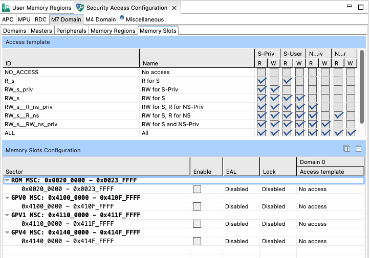
Memory Slots#
Use the Memory Slots Configuration table to configure access for a memory space:
Select the Enable checkbox.
Set the Lock to the desired state.
Set the Access Template for all listed domains.
Alternatively, you can select the options by right-clicking the master and using the dropdown list.
XRDC (eXtended Trusted Resource Domain Controller) on Cortex-A35 in i.MX8 ULP#
Masters#
XRDC masters are similar to TRDC masters. In addition, the following features are supported:
PID (Process Identifier) is combined with the PIDM field to determine the domain hit.
PIDM (PID Mask) provides a masking capability so that multiple process identifiers can be included as part of the domain hit determination. If a bit in the PIDM is set, the corresponding bit of the PID is ignored in the comparison.
PID enable provides the ability to include inclusive or exclusive sets of masked PID values. Allowed values are 00b, 01b, 10b, and 11b. For more info, see the corresponding Reference Manual.
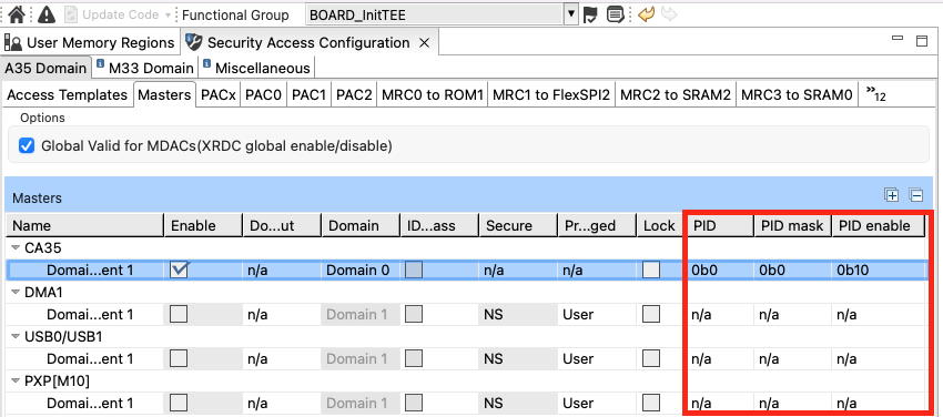
XtRDC master tab#
MRC#
MRC on XRDC is similar to MRC on TRDC. There are several minor differences:
There is only one instance of the memory regions table because address ranges are shared across all domains. For each memory region, the user can specify an access template for each domain.
The code region specifies which templates would be used (0= data, 1 = code). The templates are now hybrid. It means that there are two templates for the same ID and name – the first row is for the data region and the second row is for the code region. These templates, which have the lock field, can be edited by clicking the desired access box.
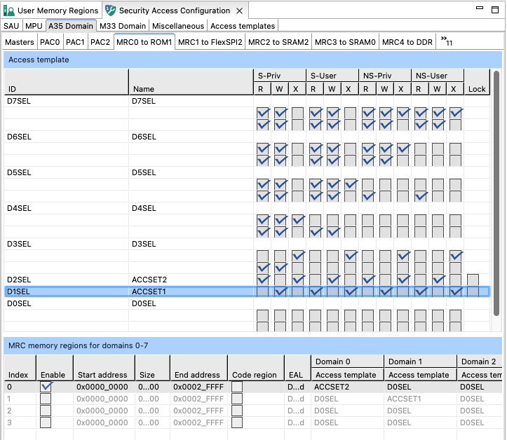
XtRDC MRC tab#
Access control modes#
There are two modes that can be enabled for PID.
For processors only supporting TSM, the Three-State Model (SecurePriv, SecureUser, NonsecureUser), the nonsecure[n] output signal from the MDAC submodule is forced to zero while in privileged mode to enable precise state transitions between the user and privileged modes. When SP4SM, the Special 4-State Model, is enabled, the MDAC does not use the MDA[DIDS,DID] fields. The MDAC tracks the current access level and generates specific domainIDs for specific access levels.
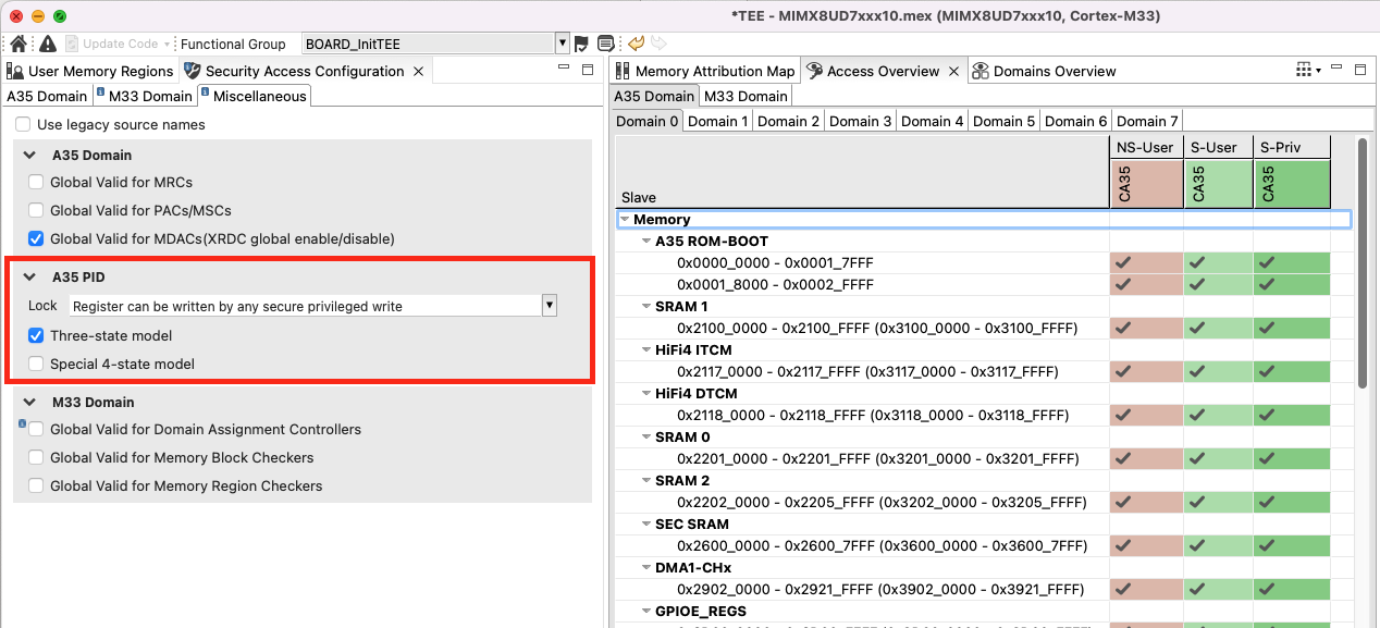
Access modes#
Trusted Resource Domain Controller on Cortex-M33 in i.MX8 ULP and KW45 (TRDC)#
The Trusted Resource Domain Controller (TRDC) provides comprehensive security management for Cortex-M33 based devices in i.MX8 ULP and KW45 processors. TRDC enables fine-grained access control through domain-based resource allocation, where chip resources are assigned to processing domains identified by unique domain identifiers (DIDs).
The TRDC configuration includes Memory Protection Unit (MPU) setup with Secure/Non-Secure register banks, domain management for resource assignment, master configuration with domain ID control, and access template management supporting both global (RDC-wide, editable) and local (checker-specific, immutable) templates. Memory access control is enforced through Memory Region Controller (MRC) for configurable memory regions and Memory Block Checker (MBC) for fixed memory blocks, providing comprehensive protection for both memory spaces and peripherals across different security domains.
MPU#
This MPU is identical to other MPUs with Cortex-M33 (for example, LPC55S) or other cores based on the Armv8-M architecture or above with Secure/Non-Secure register banks.
Domains#
The domains are similar to RDC/XRDC2/XRDC: assignment of chip resources to processing “domains”, where a unique domain identifier (domainID, DID) is assigned to each processing domain. The number of supported DIDs is typically the number of CPUs plus one.
Masters#
Masters are similar to Masters in XRDC2 on MIMXRT117x. The user can also choose the domain ID input or ID bypass depending on the master type.
Access templates#
Access templates are similar to patterns in XRDC2 on MIXRT117x. The main difference is as follows: you can switch between “global” (for the entire RDC, used by all checkers, and editable) and “local” (specific to the checker and immutable) templates; meanwhile access templates in XRDC2 are always validator-dependent and editable.
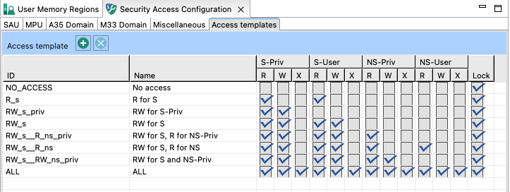
Access templates#
MRC#
MRC on TRDC is similar to MRC (Memory Regions) in XRDC2.
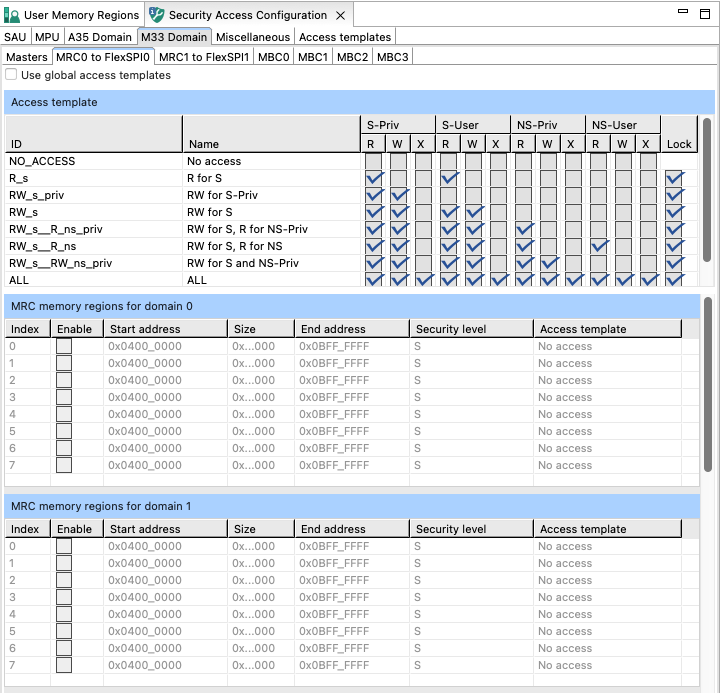
MRC#
MBC#
MBC in TRDC is similar to MSC (Memory Slots) in XRDC2 and MSC in XRDC.
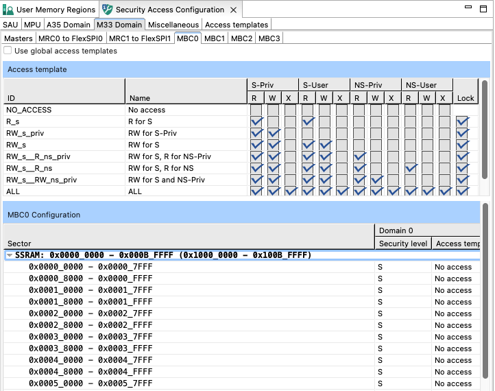
MBC#
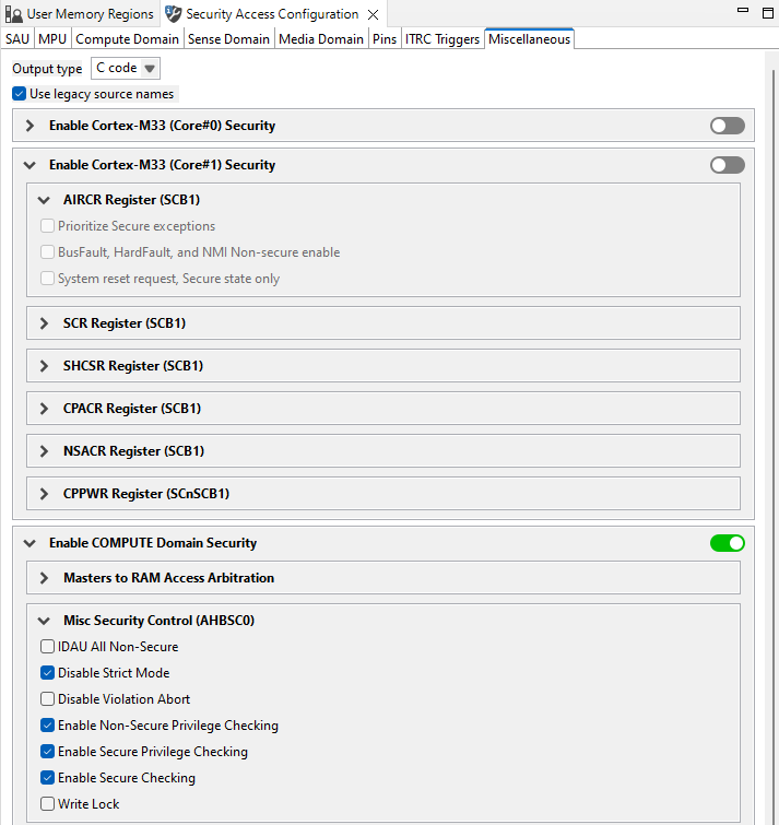
Miscellaneous#
In the Miscellaneous subview, you can set various configuration options. The list of these options depends on processor data, and varies greatly. All the options influence your register settings, and can be inspected in the Register view. Only some of the options directly influence configuration that you have made in the Security Access Configuration view. Point your cursor over individual options to display a tooltip explaining the function of each option.
A togglable checkbox enables or disables the code generation for the entire group. When the group is disabled, the code generation for that group is suspended, the generation options within it cannot be edited, and all option configurations revert to their default values (either reset values or default values).
Miscellaneous#
Memory Attribution Map#
In the Memory Attribution Map view, you can review access levels set for all masters to the code, data, and peripherals memory regions on a domain level. The table is read-only.
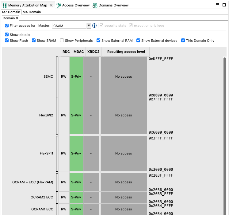
Memory Attribution Map#
To set the display options, do the following:
Click the Filter access for checkbox to enable filtering options.
Select the master that you want to review by choosing from the Master dropdown menu.
Optionally, set the security state and execution privilege check-boxes when master allows more security levels. This setting has no effect on the configuration.
Optionally, customize the output by de-selecting the Show Details, Show Flash, Show SRAM, Show Peripherals, Show External RAM, Show External Devices and This Domain Only options.
Optionally, filter displayed memory regions in the Filter area.
Point your cursor over the cells to display a tooltip with information about the security level combination.
Double-click the cell to open the pertinent settings in Security Access Configuration.
Access Overview#
In Access Overview, you can review security policies you have set in Security Access Configuration view. The view is divided into subviews displaying access overview for specific XRDC2 domains.
The vertical axis displays all masters, divided into color-coded groups by their security settings.
The horizontal axis displays memory ranges and slave buses/peripherals.
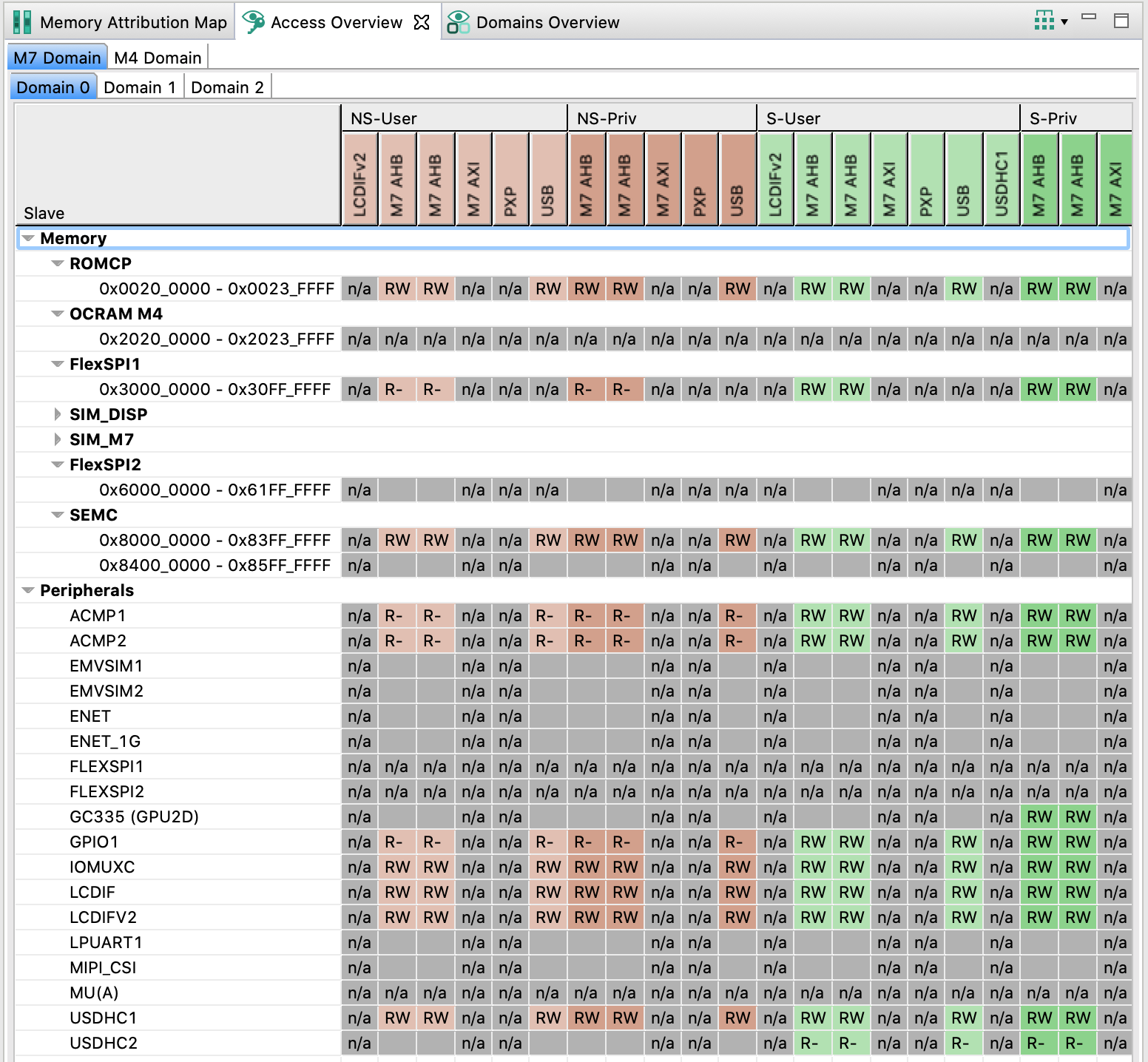
Access Overview#
Point your cursor at an entry to display a tooltip with information about the entry.
You can group the displayed information by security or by masters by using the button on the right-hand side of the toolbar.
Domains Overview#
In Domains Overview, you can review access policies of XRDC2 domains you have configured in the subviews of the Domain view.
Point your cursor over the cells to display a tooltip with information about the security level combination.
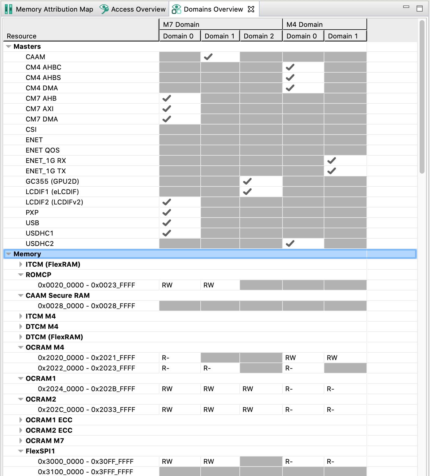
Domain Overview#
Code generation#
If the settings are correct and no error is reported, the code generation engine regenerates the source code. You can view the resulting code the Code Preview view of the Trusted Execution Environment tool.
Code Preview automatically highlights differences between the current and immediately preceding iteration of the code. You can choose between two modes of highlighting by clicking the Set viewing style for source differences. You can also disable highlighting altogether from the same dropdown menu. Such features as Copy, Search, Zoom-in, Zoom-out, and Export source are available in the Code Preview view. The search can also be invoked by CTRL+F or from the context menu.
Some AHBSC or TRDC with security extension-enabled devices support ROM preset as well as C code. You can choose to have the code generated in the ROM preset by selecting the option in the Miscellaneous subview.