
Development Guide#
This chapter provides an overview of the development workflow surrounding GUI Guider. It is designed for users who integrate the generated UI into a broader software system and supports validation on both simulators and target hardware platforms.
Debug#
Debugging a GUI Guider project goes beyond verifying that the code builds. UI behavior, resource loading, timing, and target-specific initialization must also be reviewed. A systematic debug process makes it easier to determine whether an issue originates in the UI definition, the generated code, the runtime integration, or the platform configuration.
GUI Guider supports target-side debugging through the following IDE toolchains:
MCUXpresso for VS Code (Visual Studio Code with the MCUXpresso for VS Code extension 26.2.46, using ARMGCC 14.2.1)
MCUXpresso IDE 25.6
IAR Embedded Workbench 9.60.4
Keil MDK 5.42
MCUXpresso for VS Code#
MCUXpresso for Visual Studio Code (VS Code) provides an optimized embedded developer experience for code editing, building, and debugging. It allows developers to work on projects from Zephyr or from the MCUXpresso SDK with Open-CMSIS-Packs. It supports debug connections with probes from NXP, PEmicro, and SEGGER.
This workflow uses Visual Studio Code together with the MCUXpresso for VS Code 26.2.46 extension and ARMGCC 14.2.1. For more information on NXP support for Visual Studio Code, see the MCUXpresso for VS Code Community Forum.
To install and use MCUXpresso for VS Code, perform the following steps:
Download and install Visual Studio Code from Visual Studio Code.
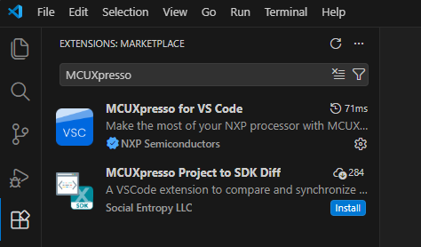
Launch VS Code. Click the Extensions icon in the left navigation pane, type “MCUXpresso” in the Marketplace search bar, and install MCUXpresso for VS Code.
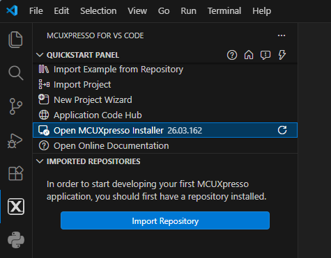
Open the extension and click Open MCUXpresso Installer. If the extension does not find the installer, it is downloaded and started automatically. The installer can also be downloaded manually from the following links:
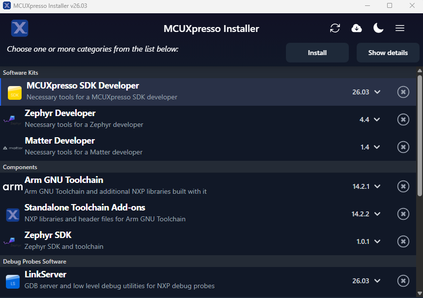
In the installer UI, select MCUXpresso SDK Developer(26.03), Arm GNU Toolchain (14.2.1), and LinkServer(26.03) from Software Kits, Components, and Debug Probes Software, and then click Install.
Confirm that all the components are installed successfully and that the message Installation completed successfully is displayed.
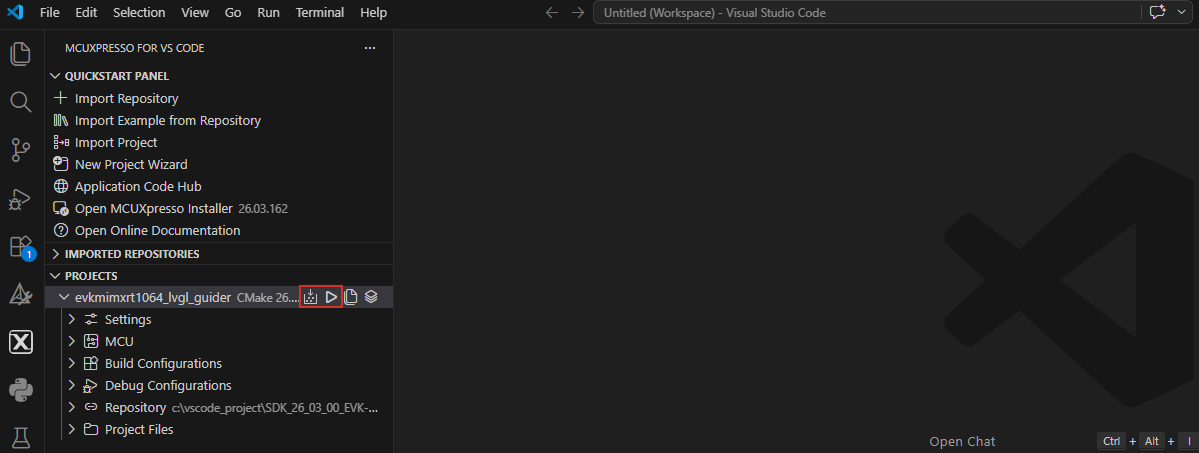
Import a project. For GUI Guider projects using the VS Code toolchain, there is a
vscodefolder under the project (GUIGuider-2.0.0/projects/<project name>/platform/vscode). Use Import Project to import this folder, and then select the Repository and Toolchain.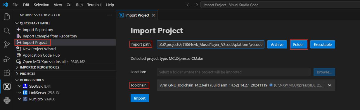
Build the project in VS Code and start a debug session.
MCUXpresso IDE#
MCUXpresso IDE is a common integration environment for NXP MCU-based embedded projects. It is typically used for project import, build, flashing, and target debugging. This workflow uses MCUXpresso IDE 25.6.
When working with this IDE, verify that the SDK and board-specific settings match the generated GUI Guider project output.
To debug a GUI Guider project with MCUXpresso IDE, perform the following steps:
Select the development board (for example, EVK-MIMXRT1064).
Select the SDK version(26.03.00) and click OTHERS.
On the Build SDK for {target} page, select the LVGL and FreeRTOS middleware components.
Make sure that MCUXpresso IDE is selected as the toolchain.
Click BUILD SDK to build the SDK.

Download and import the SDK into the IDE.
Select File > Import > General.

Select the
platform/mcuxpressopath inside the GUI Guider project using the MCUX IDE toolchain.Click Finish, build the project, and start a debug session.
IAR#
IAR Embedded Workbench 9.60.4 can be used as the target IDE when the project or organization standard requires it. After code generation, review compiler settings, memory configuration, and device setup before building the application.
To open a GUI Guider project in IAR, locate the platform/iar folder inside the project and double-click lvgl_guider*.eww.
Keil MDK#
Keil MDK 5.42 is another target-side integration option for supported devices and workflows. As with other IDEs, confirm that the generated project and the local toolchain configuration are aligned.
To open a GUI Guider project in Keil MDK, locate the platform/keil folder inside the project and double-click lvgl_guider*.uvprojx.
OS integration#
Some GUI Guider projects run in environments that include an operating system or a runtime platform layer. The following sections describe how to port a GUI Guider application to common RTOS environments and Linux.
RTOS#
In RTOS-based systems, pay attention to timing, task structure, display flush integration, and synchronization with UI updates.
Zephyr#
This section describes how to port the LVGL C source files generated by GUI Guider to Zephyr.
Set up the Zephyr development environment#
NXP provides the MCUXpresso extension for Visual Studio Code as the quickest path to learn and use Zephyr on NXP platforms. Start by reviewing the wiki. This guide uses the MCUXpresso installer to provide all required tools and dependencies for Zephyr application development and debugging. If you prefer a command-line workflow, see the Zephyr Getting Started guide.
Get Zephyr and install Python dependencies#
This GUI Guider release supports Zephyr v4.4.0 for LVGL v9 projects. Use Git commands or MCUXpresso for VS Code to check out the corresponding tag based on the LVGL version in use.
Alternatively, MCUXpresso for VS Code can be used to download Zephyr. For details, see GUI Guider example with Zephyr and MCUXpresso for VS Code.
Design the GUI and export the code#
To export the source code of a GUI application designed in GUI Guider to a Zephyr workspace, perform the following steps:
Design the GUI application in GUI Guider.
Click Generate Code to generate the GUI source.
Click OS > Zephyr to export the GUI application to the folder in the Zephyr workspace. For example, on Windows the default location is
C:\Users\<user name>\zephyrproject\gui_guider_demo.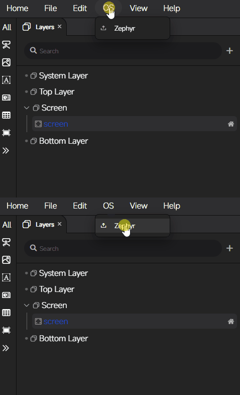
Build and deploy the Zephyr image#
To build and deploy a Zephyr image on the target board, run the following commands.
Build the Zephyr image:
cd %HOMEPATH%\zephyrproject
west build -p always -b <board> --shield <shield name> C:\Users\user1\zephyrproject\gui_guider_demo
For example, on i.MX RT1064-EVK:
west build -p always -b mimxrt1064_evk --shield rk043fn66hs_ctg C:\Users\user1\zephyrproject\gui_guider_demo
Note: For the supported boards and shields, see the Zephyr boards and shields documentation.
Deploy the Zephyr image to the target board:
To use LinkServer with the
westcommands, the install folder must be added to thePATHenvironment variable.west flash
Linux#
On Linux-based systems, it is recommended to verify display stack assumptions, file paths, permissions, deployment packaging, and startup behavior. GUI Guider provides support for building and deploying GUI applications within a Yocto-based environment.
Yocto#
The i.MX family Linux board support package (BSP) supports the Linux operating system on i.MX application processors through the Yocto project build environment. GUI Guider supports code generation for all supported i.MX boards and provides workflows for porting the GUI application to Linux.
Prerequisites#
NXP Linux Factory 6.18.2-1.0.0 release.
Linux PC.
Create a project#
On a Linux host, create a project and design the GUI application by following the standard project creation flow described in Create a New Project.
Build the GUI application binary (Linux hosts only)#
GUI Guider provides two ways to build the GUI application:
A standalone build through the GUI Guider IDE (recommended).
An exported Yocto layer that is built inside the Yocto build environment.
Standalone build using the GUI Guider IDE
In this workflow, the GUI Guider IDE invokes the Yocto toolchain to cross-compile the GUI application. Once the application binary is produced, upload it to a pre-installed Yocto rootfs and run it on the board.
Build and install the Yocto toolchain:
Download the Yocto BSP. Refer to the i.MX Yocto Project User’s Guide.
Set up the Yocto build project:
$ MACHINE=<board name> DISTRO=fsl-imx-xwayland source ./imx-setup-release.sh -b bld-<board name>
Build the Yocto toolchain:
$ echo "IMAGE_INSTALL:append = \" opencv\"" >> conf/local.conf
$ bitbake -c populate_sdk imx-image-multimedia
Install the Yocto toolchain:
$ sudo ./fsl-imx-xwayland-glibc-x86_64-imx-image-multimedia-armv8a-imx93evk-toolchain-6.18-whinlatter.sh
Install the ninja utility on the build host:
$ sudo apt install ninja-build
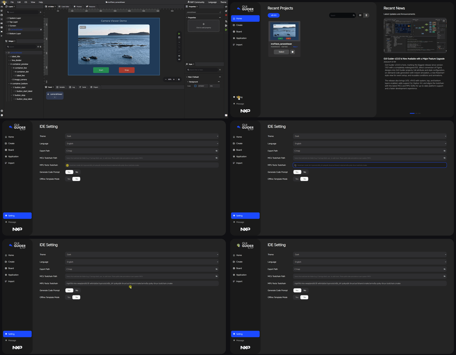
(Optional) Set the Yocto standalone toolchain path.
Select the graphic backend (DRM or Wayland).
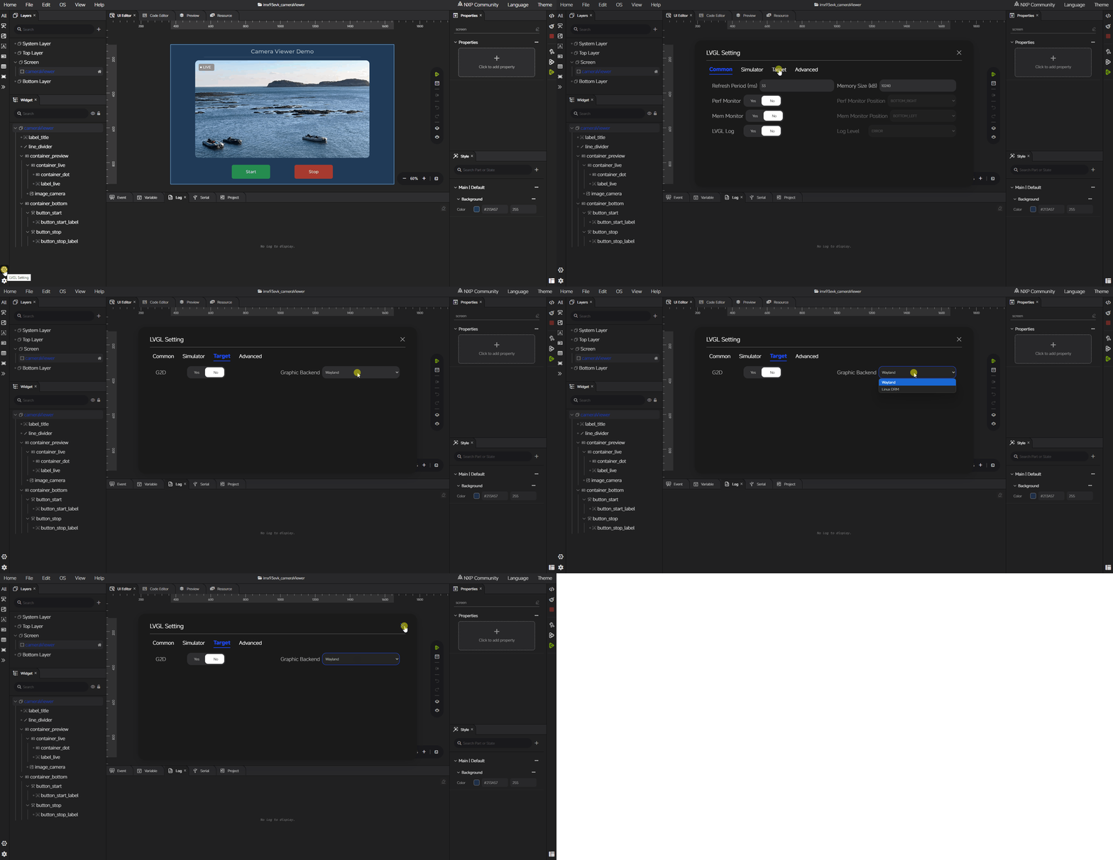
Click Generate Code.
Click Build Target to start the standalone build. The
gui_guiderbinary will be produced inside theplatform/linux/buildfolder.
If you prefer to run the standalone build outside the GUI Guider IDE:
Click Generate Code in GUI Guider.
Open a Linux terminal and go to the GUI Guider project folder.
Check and update the toolchain path in
platform/linux/build.shif a different toolchain is used.Run the standalone build:
$ bash platform/linux/build.sh
Export the Yocto layer and build in Yocto
The GUI Guider IDE can also export a Yocto layer that includes the GUI application code and the corresponding Yocto recipes. Plug the exported layer into an existing Yocto build environment and use bitbake to build the gui_guider binary.
Export the Yocto layer:
Click Generate Code to generate the code.
Click OS > Yocto to export the Yocto layer.
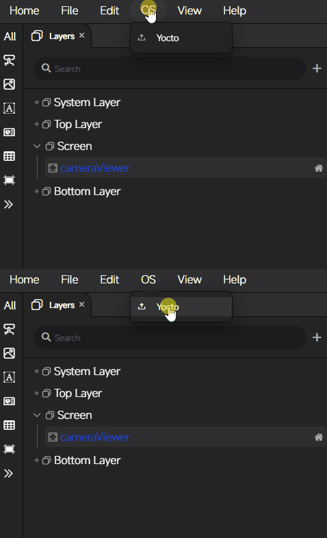
Note: The
meta-gui-guiderfolder is the Yocto layer used as a plug-in for the Yocto SDK.
Build the GUI application in Yocto:
Copy the exported
meta-gui-guiderfolder to<path>/imx-bsp/sources/.Build with Yocto:
First-time build (after setting up the Yocto project):
$ bitbake-layers add-layer ../sources/meta-gui-guider
$ echo "INHERIT += \"rm_work\"" >> conf/local.conf
$ echo "RM_WORK_EXCLUDE += \"gui-guider\"" >> conf/local.conf
$ bitbake gui-guider
Subsequent builds:
$ source ./setup-environment bld-<board name>
$ bitbake gui-guider
Note: The
gui_guiderbinary is produced in<path>/imx-bsp/bld-<board name>/tmp/work/armv8a-poky-linux/gui-guider/<version>/build/.
Additional configuration for the Camera Viewer (Linux) demo
The Camera Viewer (Linux) demo requires extra Yocto configuration. Apply the following two steps only when using this demo.
Enable the camera feature by adding the following line to
conf/local.conf:GG_FEATURES = "camera"
The demo depends on OpenCV, so rebuild the
imx-image-multimediarootfs with OpenCV:$ echo "IMAGE_INSTALL:append = \" opencv\"" >> conf/local.conf $ bitbake imx-image-multimedia
Run the GUI application#
This section describes how to deploy and run GUI applications on i.MX Evaluation Kit (EVK) boards. To use a supported display panel, load the corresponding device tree blob (DTB) file that contains the panel’s hardware configuration. The DTB files for typical boards are:
Board |
DTB |
|---|---|
MCIMX8ULPEVK |
imx8ulp-evk.dtb |
MCIMX91LP4EVK |
imx91-11x11-evk-tianma-wvga-panel.dtb |
MCIMX91LP4QSB |
imx91-9x9-qsb-tianma-wvga-panel.dtb |
MCIMX91FRDM |
imx91-11x11-frdm-tianma-wvga-panel.dtb |
FRDM-MCIMX91S |
imx91-11x11-frdm-imx91s-tianma-wvga-panel.dtb |
MCIMX93EVK |
imx93-11x11-evk-boe-wxga-lvds-panel.dtb |
MCIMX93FRDM |
imx93-11x11-frdm-tianma-wvga-panel.dtb |
IMX943LPD5EVK-19 |
imx943-evk.dtb |
IMX95LPD5EVK-19 |
imx95-19x19-evk-jdi-wuxga-lvds-panel.dtb |
Deploy the image on an SD card:
$ zstd -d -f imx-image-multimedia-imx93evk.wic.zst
Note: If the
zstdcommand is not installed, install it withsudo apt-get install zstd.sudo dd if=imx-image-multimedia-imx93evk.wic of=/dev/sdx bs=4M && sync
Insert the SD card into the i.MX 93 EVK.
Power on, boot to U-Boot, set the DTB, and reset the board:
=> setenv fdtfile imx93-11x11-evk-boe-wxga-lvds-panel.dtb
=> saveenv
=> reset
Boot to Linux.
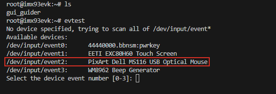
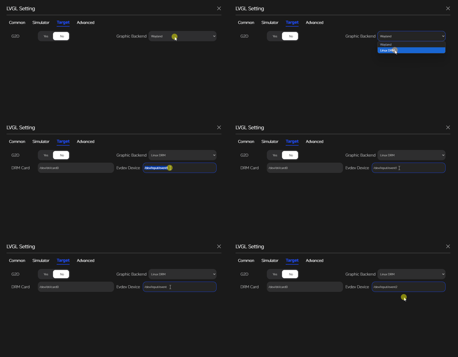
Note: If the DRM backend is used, check and set the EVDEV device.
Check the EVDEV device in the terminal:
Set the EVDEV device in the GUI Guider project setting:
Build and upload the
gui_guiderbinary to the board.Run the GUI application:
$ ./gui_guider&
Note: When the DRM backend is used, ensure that the Weston service is stopped by running
systemctl stop westonbefore launching the GUI application.
Storage and file system#
Some GUI Guider projects use external assets or runtime-loaded resources. In these cases, define a clear storage strategy early and verify that resource paths remain consistent from development to deployment.
LVGL supports the following image sources:
A variable in code (a C array of pixels).
A file stored externally, for example on an SD card or in QSPI flash.
A text with symbols.
An attractive GUI relies on well-designed images, and complex UIs require more of them. When the selected MCU does not have enough internal flash, storing images externally is a way to fit the application within the available flash.
GUI Guider currently supports the following external image sources:
Images in PNG, JPG, BMP, or binary format on an SD card with the FatFs file system.
Images in binary format in QSPI flash with the memory-mapped file system.
SD card#
The SD card can hold image assets that are decoded at runtime by image-related widgets.
Images on the SD card#
Images (BIN, BMP, JPG, PNG) can be stored on an SD card and used by image-related widgets (Image Button, Image, Animation Image). The images are decoded at runtime.
The JPG (SJPG) format does not support zoom or rotation when decoded from external storage. Use the PNG format instead if those operations are required.
Prerequisites
Connect the supported device to the host with a USB cable.
Project template
GUI Guider provides an application template(SD Card Storage) for supported boards. Usage tips are displayed on the screen.
Create a project by selecting a supported board and the SD Card Storage application template.
The image files are located in the
resources/imagefolder.SD card storage can be enabled in the property settings of image-related widgets.
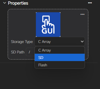
Copy the images to the SD card. When SD card storage is enabled, the SD path must match the actual folder layout on the SD card.
Note: For the LVGL file system, use a single
/as the path separator.
Customized project
To store images on the SD card from a custom project, perform the following steps:
Drag the widget into the editor and configure its properties.
Open the project folder and locate the
resources/imagefolder. Identify the image files to store on the SD card and copy them to the SD card.Note: All image files used by
Animation Imagemust be in the same folder on the SD card.Enable SD Storage Type in the widget property window and enter the absolute path of the folder that contains the images.
Insert the SD card into the MCU device. To deploy the application, click Deploy Target.
QSPI flash#
This section describes how to place images in QSPI flash, using the i.MX RT1060-EVK as an example.
Add image-related widgets and set properties#
Set the flash address used to store the image binary.
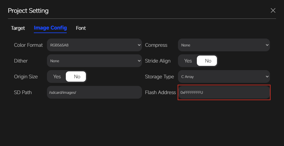
Flash storage can be enabled in the property settings of image-related widgets.
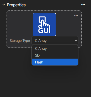
Build and deploy#
Click Generate Code to generate the GUI source and image binaries. The
mergeBinFile.binbinary will be produced inside thegenerated/assets/imagesfolder.Click Deploy Target to deploy the application.
Program
mergeBinFile.binto the flash address specified in the previous step.Reset the board. The image should display correctly.
Industrial HMI with Real-time Edge#
Industrial HMI projects often involve more demanding requirements for responsiveness, maintainability, and integration with real system data. In such projects, GUI Guider is most effective when used as one part of a structured system architecture.
Industrial HMI with Real-time Edge leverages NXP’s Real-time Edge software to deliver responsive, low-latency human-machine interfaces for industrial environments. By using Preempt-RT Linux, RTOS, and BareMetal frameworks on heterogeneous multicore and multi-SoC platforms, it ensures fast data processing and real-time control.
This solution supports a rich set of industrial networking protocols, including EtherCAT, CANopen, and Modbus, enabling integration with sensors, encoders, and field devices. Combined with optimized graphics and unified life cycle management across cores, it provides a robust foundation for reliable, high-performance industrial HMI systems.
For more information, visit the Real-Time Edge website.
Industrial HMI application setup#
This section provides step-by-step instructions for setting up an industrial HMI application based on NXP Real-time Edge V3.4.
Prerequisites
NXP Real-time Edge V3.4 image
MCIMX93FRDM
SD card (8 GB minimum recommended)
SD card reader/writer
Linux host computer for preparation
Setup instructions
Deploy the pre-built SD card image:
Download the Real-time Edge V3.4 image (
REAL-TIME_EDGE_V3.4_IMX93-11XI-LPDDR4-FRDM) from the NXP download page.Flash the image to the SD card, for example using Balena Etcher or
dd:unzip Real-time_Edge_v3.4_IMX93-11X11-LPDDR4X-FRDM.zip cd Real-time_Edge_v3.4_IMX93-11X11-LPDDR4X-FRDM/real-time-edge zstd -d -f nxp-image-real-time-edge-imx93-11x11-lpddr4x-frdm.rootfs.wic.zst sudo dd if=nxp-image-real-time-edge-imx93-11x11-lpddr4x-frdm.rootfs.wic of=/dev/sdX bs=4M && sync
Copy the DTB file. Insert the SD card into the target board and power it on. Copy the required DTB file from the
custom/dtbdirectory to the boot partition:sudo cp custom/imx93-11x11-frdm-multicore-rtos-waveshare-7inch-c-panel.dtb /run/media/$USER/boot-mmcblk1p1/
Configure the U-Boot environment:
Insert the SD card into the target board and power it on.
Interrupt the boot process to enter the U-Boot console.
Set the DTB and save the environment:
setenv fdtfile imx93-11x11-frdm-multicore-rtos-waveshare-7inch-c-panel.dtb
setenv mmcargs $mmcargs clk_ignore_unused
saveenv
Upload the application files to the target board:
scp -r custom/elf/ root@<board-ip>:/path/to/destination/
scp -r custom/script/* root@<board-ip>:/path/to/destination/
Click Generate Code in GUI Guider.
Click Build Target in GUI Guider and upload the
gui_guiderbinary:scp -r platform/linux/build/gui_guider root@<board-ip>:/path/to/destination/
Run the application:
Note: Before running the application, restart the Weston service to avoid issues related to service state or configuration.
systemctl restart weston
./gui_guider
The expected file structure is:
.
├── elf/
├── gui_guider
├── start.sh
└── stop.sh
Troubleshooting
If the display does not work, verify that the correct DTB file is in use.
For input device issues, check the input device paths in your configuration.
Inspect system logs for error messages:
dmesg | tail
Yocto build with Real-time Edge#
This section provides step-by-step instructions for building a Yocto environment with GUI Guider support for the MCIMX93FRDM using the Real-time Edge V3.4 distribution.
Prerequisites
Git and the
repotool installed.Sufficient disk space (50 GB minimum recommended).
A properly configured Linux build environment.
MCIMX93FRDM
NXP Real-time Edge V3.4 image.
Download Real-time Edge V3.4 and initialize the workspace:
mkdir yocto-real-time-edge-v3.4
cd yocto-real-time-edge-v3.4
repo init -u https://github.com/nxp-real-time-edge-sw/yocto-real-time-edge.git -b real-time-edge-walnascar -m real-time-edge-3.4.0.xml
repo sync
Set up the build environment for the MCIMX93FRDM:
DISTRO=nxp-real-time-edge MACHINE=imx93-11x11-lpddr4x-frdm source real-time-edge-setup-env.sh -b build-imx93-frdm
Note: For detailed setup instructions, see the Real-Time Edge v3.4 README.
Add the GUI Guider meta layer:
Copy the exported
meta-gui-guiderfolder to the sources directory:cp -r /path/to/meta-gui-guider ./sources/
Add the layer to the build environment:
bitbake-layers add-layer ../sources/meta-gui-guider
Configure the build and build GUI Guider:
echo "INHERIT += \"rm_work\"" >> conf/local.conf
echo "RM_WORK_EXCLUDE += \"gui-guider\"" >> conf/local.conf
bitbake gui-guider
Build configuration explanation:
INHERIT += "rm_work": Enables automatic cleanup of temporary work directories to save disk space.RM_WORK_EXCLUDE += "gui-guider": Keeps thegui-guiderpackage out of automatic cleanup, preserving build artifacts for debugging.
After a successful build:
Upload the generated binary to the MCIMX93FRDM.
Verify GUI Guider application functionality on the board.
Refer to the application documentation for usage details.
Peripheral and data integration#
Real applications often need to reflect hardware state, communication data, or external inputs in the UI. A clean integration model helps keep UI logic understandable and prevents low-level implementation details from leaking into the generated UI code.
In a typical GUI Guider project, peripheral and data integration is handled outside the generated UI files. Application code reads data from peripherals or communication interfaces, updates shared variables or state, and then drives UI updates through the standard widget and event APIs.
Recommended practices include:
Keep peripheral access in custom code: Place hardware access, communication, and data parsing logic in the project’s
customdirectory or in application-level files, rather than inside generated screen or event code.Use shared variables or state objects: Expose only the values the UI needs through clearly defined variables. Examples include sensor readings, connection status, and mode flags. This approach keeps the UI layer independent of data acquisition logic.
Update the UI on a controlled cadence: Refresh widget values from a periodic task, a timer, or an event callback. Avoid blocking peripheral operations on the UI thread.
Separate UI logic from protocol details: Keep transport-specific code (UART, SPI, I2C, Ethernet, CAN, and similar) behind a thin abstraction so that the UI does not depend on a specific peripheral implementation.
Detailed guidance for specific peripheral types and integration scenarios will be added in later revisions of this chapter.