
Clocks Tool#
The Clocks Tool configures initialization of the system clock (core, system, bus, and peripheral clocks) and generates the C code with clock initialization functions and configuration structures.
Features#
The Clocks tool allows you to perform various actions related to the clock initialization, including the following:
Inspect and modify element configurations on the clock path from the clock source up to the core/peripherals.
Validate clock elements settings and calculate the resulting output clock frequencies.
Generate a configuration code using the SDK.
Modify the settings and provide output using the table view of the clock elements with their parameters.
Navigate, modify, and display important settings and frequencies easily in Diagram view.
Edit detailed settings in Details view.
Inspect the interconnections between peripherals and consuming clocks in Module Clocks view.
Find clock elements settings that fulfill given requirements for outputs.
Fully integrated in tools framework along with other tools.
The tool shows configuration problems in the Problems view and guides the user to the resolution.
Register values define generation of C.
User interface overview#
The Clocks tool is integrated and runs within the MCUXpresso Config Tools framework.
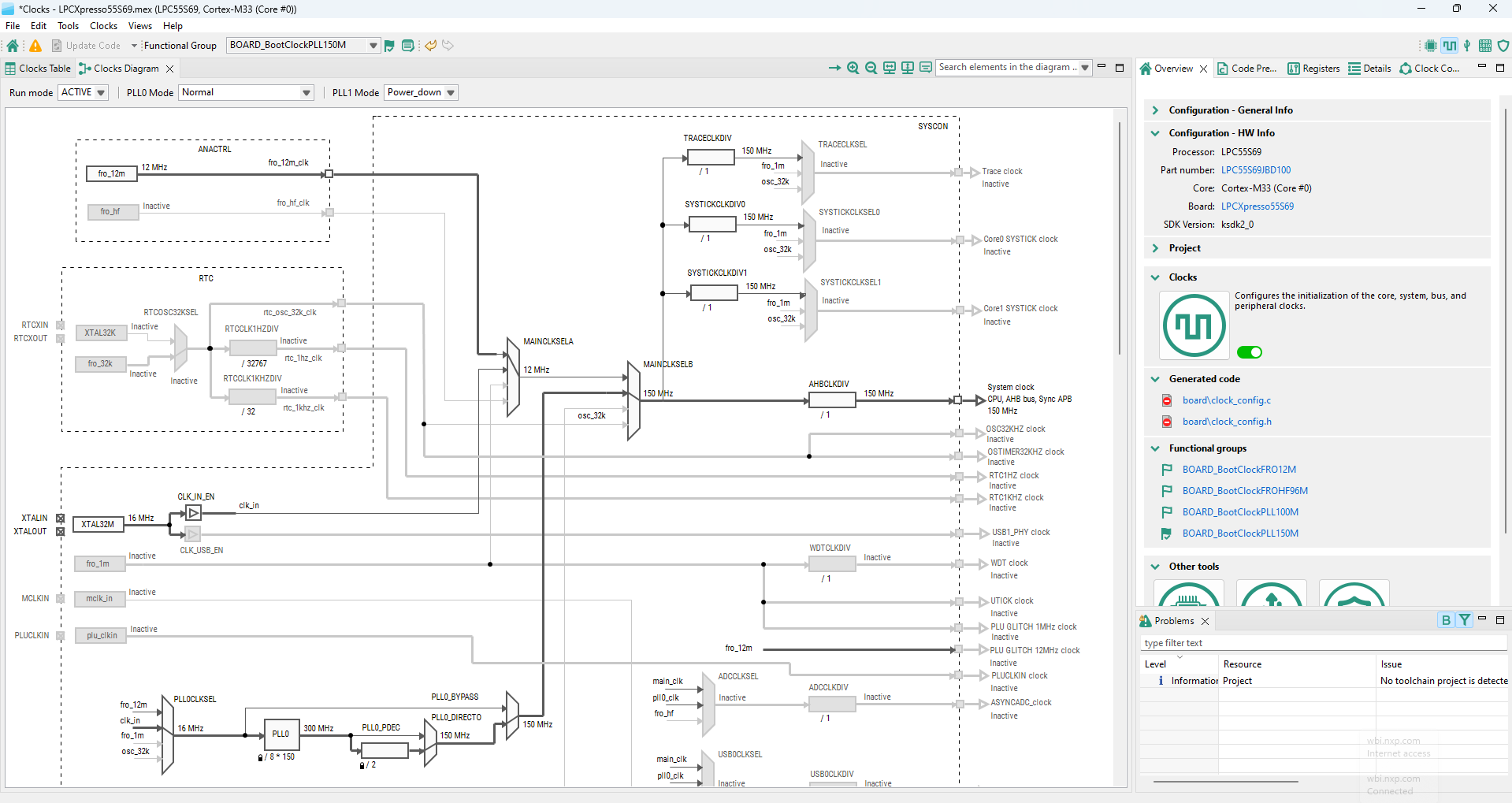
User interface clocks#
Details view#
The Details view displays clock-element settings information and allows you to change it.
The information is also updated in real-time based on any changes in the Clocks Diagram and Clocks Table.
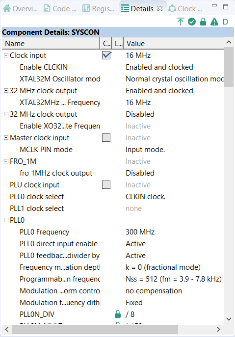
Details view#
In the Details view, you can perform the following actions:
Display clock-element information - Point the mouse cursor at the clock element to display general clock-element information.
View the clock-element in Clocks Diagram or Clocks Table - Left-click on a clock element to highlight it in the Clocks Diagram or Clocks Table views, depending on which is currently active.
View detailed clock-element information - Double-click a clock element to display element details, as well as highlight the element in Clocks Diagram or Clocks Table, depending on which is currently active. You can also view element details by clicking the Open in new window button in the upper right corner of the Details view.
Modify clock-element settings - Left-click in the Value column to change clock element value, such as frequency, or select an option from the dropdown menu.
Lock/unlock clock elements - Right-click on a clock element to lock/unlock the element.
Filter for active/locked/erroneous clock elements - Use the buttons in the upper-right corner of the Details view to filter for active/locked/erroneous clock elements, or to remove all current filters.
Clock consumers view#
The Clock Consumers view provides an overview of peripheral instances. It also provides information on clock-clock instance pairing. This view is not editable and is for information only.
Note: Information about which peripherals are consuming which output clock is available in the clock output tooltip.
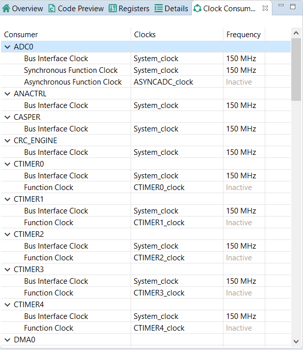
Clock Consumers view#
Clocks diagram#
The clocks diagram shows the structure of the entire clock model, including the clock functionality handled by the tool. It visualizes the flow of the clock signal from clock sources to clock output. It is dynamically refreshed after every change and always reflects the current state of the clock model.
At the same time, it allows you to edit the settings of the clock elements.
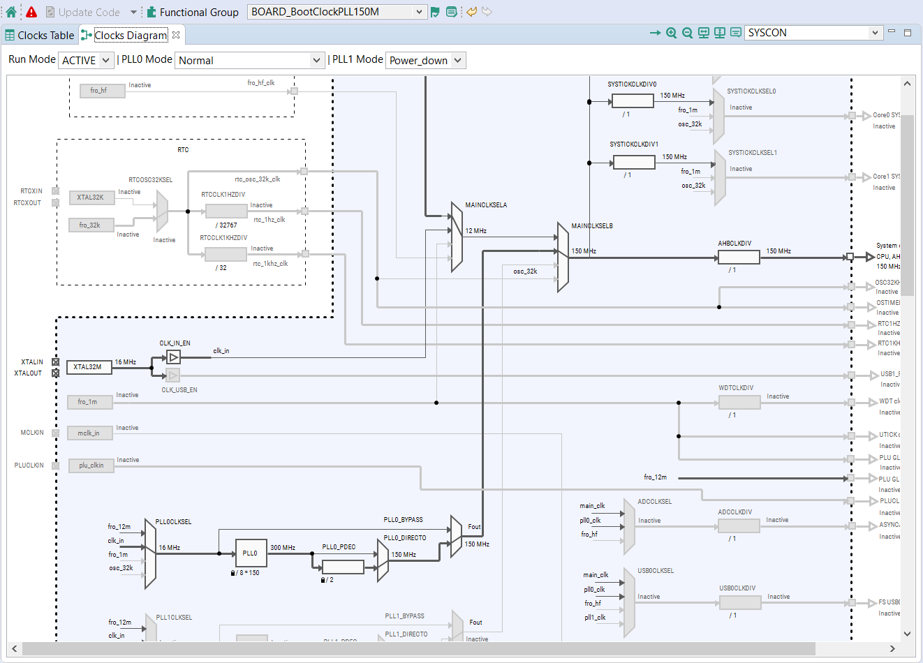
Clocks diagram#
Mouse actions in diagram#
You can perform the following actions in the Clocks Diagram view.
Position the mouse cursor on the element to see the tooltip with the information on the clock element such as status, description, output frequency, constraints, and enable/disable conditions.
Single-click on output frequency or scale to change output frequency or scale.
Single-click on lock to remove the lock.
Double-click the element to show its settings in the Details view (force to open the view if closed or not visible).
Single-click on the element to show its settings in the Details view.
Single-click on a selected Clock source to display a dropdown menu for enabling or disabling the source.
Single-click on a selected Clock selector to display selector input options.

Clocks mouse actions in diagram#
Right-click the element, component, or clock output to see a pop-up menu with the following options.
Edit settings of: {element} – Invokes the floating view with the settings for a single element.
Edit all settings – Invokes the floating view with all the settings for an element.
Edit settings on the path to: {clock output} – Invokes the floating view with the settings for all elements on the clock path leading to the selected clock output.
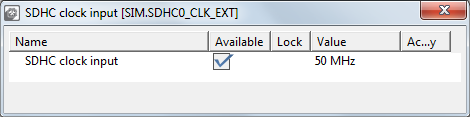
Floating view#
Color and line styles#
Different color and line styles indicate different information for the element and clock signal paths.
The color and line styles can indicate:
Active clock path for selected output
Clock signal path states - used/unused/error/unavailable
Element states – normal/disabled/error
To inspect colors and style appearance, select Help > Show diagram legend from the main menu.
Clock model structure#
The clock model consists of interconnected clock elements. The clock signal flows from the clock sources through various clock elements to the clock outputs. The clock element can have specific enable conditions that can stop the signal from reaching the successor. The clock element can also have specific constraints and limits that the Clocks Tool monitors. To inspect these details, position the cursor on the element in the clock diagram to display the tooltip.
The following are the clock model elements.
Clock source – Produces a clock signal of a specified frequency. If it is an external clock source, it can have one or more related pins.
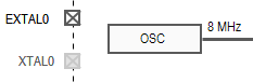
Clock source#
Clocks selector (multiplexer) – Selects one input from multiple inputs and passes the signal to the output.
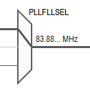
Clocks selector#
Prescaler – Divides or multiplies the frequency with a selectable or fixed ratio.
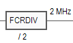
Prescaler#
Frequency Locked Loop (FLL) – Multiplies an input frequency with a given factor.
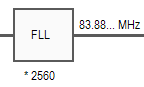
Frequency Locked Loop#
Phase Locked Loop (PLL) – Contains a pre-divider and therefore can divide or multiply with a given value.
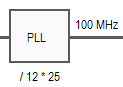
Phase Locked Loop#
Clock gate - Stops the propagation of an incoming signal.
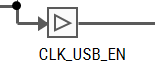
Clock gate#
Clock output – Marks the clock signal output that has a name and can be used by the peripherals or other parts of the processor. You can add a lock and/or frequency request.

Clock output#
Clock component – Group of clock elements surrounded with a border. The clock component can have one or more outputs. The clock component usually corresponds to the processor modules or peripherals. The component output may behave like clock gates, allowing or preventing the signal flow out of the component.
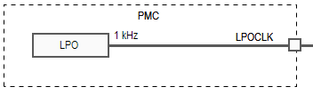
Clock component#
Configuration element – Additional setting of an element. Configuration elements do not have graphical representation in the diagram. They are shown in the setting table for the element or the clock path the element is on.
Clock configuration#
Each clock configuration (functional group) lists the settings for the entire clock system and is a part of the global configuration stored in the MEX file. Initially, after you create the new clock configuration, it reflects the default after-reset state of the processor.
There can be one or more clock configurations handled by the Clocks tool. The default clock configuration is created with the name “BOARD_BootClockRUN”. Multiple configurations provide multiple options for processor initialization.
Note: All clock settings are stored individually for each clock configuration so that each clock configuration is configured independently.
Clock configurations (functional groups) are shown at the top of the view. You can switch between them by selecting them from the dropdown menu.

Default clock configuration#
Note: The code generation engine of the tool generates a function with the name derived from the Clock configuration name.
Global settings#
Global settings, such as Run Mode and MCG mode, influence the entire clock system. It is recommended to set them first. Global settings can be modified in Clock Table, Clock Diagram, and Details views, and the Functional group properties dialog.
Note: Global settings can be changed at any time.

Global settings#
Clock sources#
The Clock Sources table is in the Clocks Table view. You can also edit the clock sources directly from the Diagram view or from the Details view.
You can configure the availability of external clock sources (check the checkbox) and set their frequencies. Some sources can have additional settings available when you unfold the node.
If the external crystal or the system oscillator clock is available, check the checkbox in the clock source row and specify the frequency.
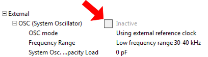
External clock source configuration#
Note: Some clock sources remain inactive even though the checkbox is checked. This is because the clock source functionality depends on other settings such as power mode or additional enable/disable options. You can hover over the setting to see a tooltip with information on the element and possible limitations.
Setting states and markers#
The following states, styles, and markers reflect the information shown in the setting rows in the settings tables (clock sources, output, details, or individual).
Table setting states and markers#
State/Style/Marker |
Icon |
Description |
|---|---|---|
Error marker |
|
Indicates that there is an error in the settings or something related to it. See the tooltip of the setting for details. |
Warning marker |
|
Indicates that there is a warning in the settings or something related to it. See the tooltip of the setting for details. |
Lock icon |
|
Indicates that the settings (that may be automatically adjusted by the tool) are locked to prevent any automatic adjustment. If a setting can be locked, it is automatically locked when you change the value. To add/remove the lock manually, use the pop-up menu command Lock/Unlock.Note: The clock element settings that cannot be automatically adjusted by the tool keep their value as is and do not allow locking. They are: clock sources, clock selectors, and configuration elements. |
Yellow background |
|
Indicates that the field is directly or indirectly changed by the previous user action. |
Gray text |
|
Indicates that the value of a setting does not actively influence the clock. It is disabled or relates to an inactive clock element. For example, on the clock path following the unavailable clock source or disabled element. The frequency signal also shows the text “inactive” instead of frequency. The value is also gray when the value is read-only. In such a state, it is not possible to modify the value. |


Frequency settings#
The Clocks tool instantly recalculates the state of the entire clock system after each change of settings from the clock source up to the clock outputs.
The current state of all clock outputs is listed in the Clock Outputs view on the right side of the clock sources. The displayed value can be:
Frequency – Indicates that a clock signal is active and the output is fed with the shown frequency. The tool automatically chooses the appropriate frequency units. In case the number is too long or has more than three decimal places, it is shortened and only two decimal places are shown, followed by an ellipsis (‘…’), indicating that the number is longer.
“Inactive” text – Indicates that no clock signal flows into the clock output or is disabled due to some setting.
If you have a specific requirement for an output clock, click the frequency you would like to set, change it, and press Enter.

Setting the core clock frequency#
If the tool has reached the required frequency, it appears locked and is displayed as follows:

Tool attains the required frequency#
If the tool cannot reach the required frequency or another problem occurs, it is displayed as follows:

Tool encounters problem#
The frequency value in square brackets [ ] indicates the value that the tool uses in the calculations instead of the requested value.
Note: You can edit or set requirements only for the clock source and the output frequencies. You can adjust the other values only when no error is reported.
Pop-up menu commands#
To access the menu, right-click on the clock output in the clocks view or in the diagram.
Lock/Unlock – Removes the lock on the frequency, which enables the tool to change any valid value that satisfies all other requirements, limits, and constraints.
Find Near Valid Value – Tries to find a valid frequency that lies near the specified value, if the tool fails to reach the requested frequency.
Advanced resolver for {Clock output} - Invokes more advanced search for the valid settings that fulfills the requirements. It may take significant time, so the tool shows a progress dialog. If the resolver is not successful, the tool notifies the user. This command can alter clock selectors and modify various other clock settings on the clock path. If the result is not satisfactory, use the
UNDOcommand to return to the original state.Edit settings of: {element} – Invokes the floating view with the settings for a single element.
Edit all settings – Invokes the floating view with all the settings for an element.
Edit settings on the path to: {clock output} – Invokes the floating view with the settings for all elements on the clock path leading to the selected clock output.

Pop-up commands for outputs in the clocks table view#

Pop-up commands for outputs in the clocks diagram#
Frequency precision#
For locked frequency settings (where the user requests a specific value), the frequency precision value is also displayed. By default, the value is 0.1 %, but can be individually adjusted by clicking the value.

Frequency precision#
Dependency arrows#
In the Clocks Table view, the area between the clock sources and the clock output contains arrows directing the clock source to outputs. The arrows lead from the current clock source used for the selected output into all outputs that are using the signal from the same clock source. This identifies the dependencies and the influences when there is a change in the clock source or elements on a shared clock path.

Dependency arrows#
Modular clock initialization#
Some MCUs support clock initialization per a clock module. In this case, there is a generated function (InitClockModule ) that can be used to initialize clock modules separately. This function is also used by the generated initialization function for the current functional group.
The usage of the module initialization function can be configured independently for each module via the Modular Initialization view.
Modular Initialization view#
This view is displayed only for MCUs that support modular initialization. This view is shown in Figure Modular Initialization view.
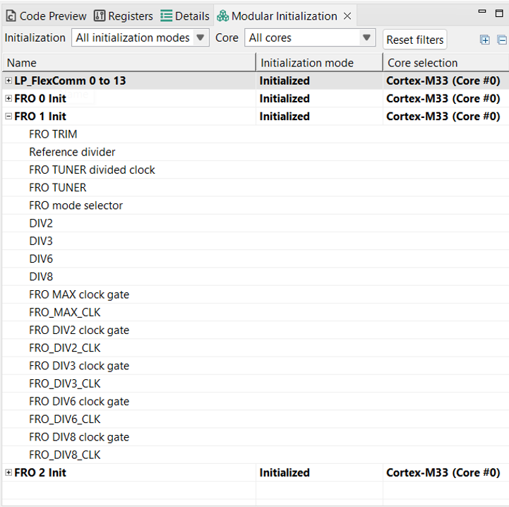
Modular Initialization view#
The view contains a table with an expandable list of all clock initialization modules on the MCU in the current functional group. When the modules are expanded using the expand/collapse icon on the left, a list of all clock elements that are parts of the module is shown. Double-click to see the Details view, where the double-clicked element is focused and selected. This selection propagates to the clock diagram and other views.
The table has the following columns:
Name is the name of the clock module.
Initialization mode shows how the initialization of the clock module is handled. The following values are available:
Initialized: the code of the initialization function for the module is generated and the module initialization function is called from the functional group initialization function.
Runtime: the code of the module is generated, but it is not called from the initialization function for this functional group. Call the module initialization function (
InitClockModule) for this module if needed during the runtime.Custom: the initialization code for that module is not generated. The user must handle its initialization entirely.
Core selection selects the core that handles the initialization of the clock module. As the Clocks tool generates independent files for each core, this determines in which file the code is generated.
Details view#
For the supported MCUs, the Details view shows an additional column Init Module. See Figure Details view extended with Init Module column.
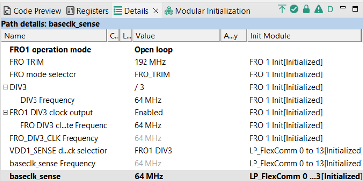
Details view extended with Init Module column#
The Init Module column displays the clock initialization module of the clock element in the corresponding row if the element belongs to a module. The module name is followed by the value of the initialization mode in square brackets. When the clock output is selected, all initialization modules that affect the clock element on the path to the corresponding clock output are visible.
Double-click on an initialization module to switch to the Modular Initialization view where the module is selected and expanded.
Clock diagram#
To alert the user of the potential of non-initialized clock output, the Clock Diagram shows a yellow marker next to the affected clock output. This marker highlights the clock elements on the path to the marked clock output belonging to a clock module in a non-default initialization mode (runtime or custom). The tooltip of that clock output displays information about the initialization modules that are in the nondefault initialization state. This feature can be seen in Figure Yellow marker in clock diagram informing about nondefault initialization mode.

Yellow marker in clock diagram informing about nondefault initialization mode#
Troubleshooting problems#
It is possible that problems or conflicts occur while working with the Clocks Tool. Such problems and the overall status are indicated in red on the central status bar of the Clocks Tool. The status bar displays global information on the reported problem.
You may encounter any of the following problems:
Requirements not satisfiable: Indicates that there are one or more locked frequency or frequency constraints for which the tool is not able to find a valid setting and satisfy those requirements.
Invalid settings or requirements: [element list] – Indicates that the value of a setting is not valid. For example, the current state of settings is beyond the acceptable range.
The following are some tips to troubleshoot encountered problems:
Start with only one locked clock output frequency and let the tool find and calculate other ones. After you are successful, you can add more.
Go through the locked outputs (if there are any) and verify the requirements (there can possibly be typos in the required frequency, wrong units, and so on).
If you want to enable a clock output, use the pop-up menu command Enable, which automatically finds settings that provide a valid frequency on the clock output.
If the required clock output value cannot be satisfied, use the pop-up menu command “Advanced resolver for {clock output}”.
If you want a frequency value close to the requested value but want to keep the clock selectors and clock sources unchanged, right-click and from the pop-up menu select Clock output > Find near value.
If the problems still persist, find the elements and settings with marked errors in the diagram or tables and see the details in the tooltip.
If you cannot reach the values you need, use the diagram view to see the elements on clock path leading to the clock output you want to have set. Try to check and adjust the settings of these elements manually in the Details view.
Try to remove locks by selecting Clocks > Unlock All Settings. In case too many changes are required and conflicting, you can simply reset the model to the default values and start from the beginning. To reset, select Clocks > Reset to processor defaults.
You can resolve most of the reported problems using the Problems view. Each problem is listed as a separate row. The following options appear when you right-click on a selected row in the Problems view.
Show problem - Shows the problem in the Clocks Diagram view.
If one of the solutions is possible, then the pop-up is extended by:
Remove lock - Removes the lock from erroneous element.
Find Near value - Finds the nearest value.
Enable- If the clock output is disabled, tries to find settings that provide valid frequency on the clock output.
Advanced resolver - Invokes the advanced resolver that tries to find suitable settings to achieve the required frequency. For more information, see the Advanced resolver in the pop-up menu commands.
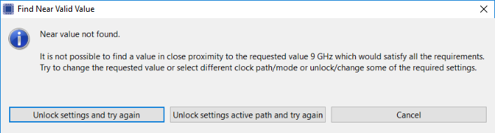
Find Near Value Dialog#
-   **Unlock settings active path and try again** - unlocks all elements that lead to selected output and tries to recompute.
-   **Unlock settings and try again** - unlocks all locked values and tries to recompute. If automatic value computation fails, nothing is changed.
-   **Cancel** - cancels the modifications.
Code generation#
If the settings are correct and no error is reported, the code generation engine instantly regenerates the source code. The resulting code appears in the Code Preview view.
Code Preview automatically highlights differences between the current and immediately preceding iteration of the code. You can choose between two modes of highlighting by clicking Set viewing style for source differences. You can also disable highlighting altogether from the same dropdown menu. The Copy, Search, Zoom-in, Zoom-out, and Export source features are available in the Code Preview view. The search can also be invoked by pressing CTRL+F or from the context menu.
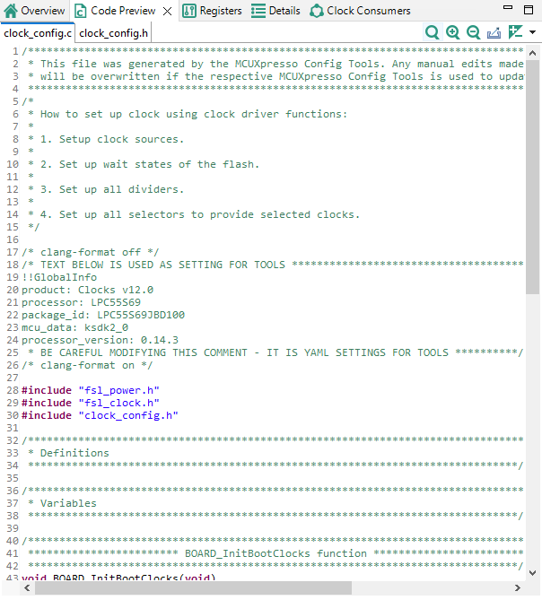
Code Preview Clocks#
Working with the code#
The generated code aligns with the SDK. To use the code with the SDK project, transfer the code into your project structure.
To transfer the code into your project, do one of the following in the Code Preview:
Click Update Code in the toolbar.
Copy the content using the COPY command, either by pressing CTRL+C or by right-clicking the pop-up menu after selecting all text.
Use the export command.
Click the Export button in Code Preview view.
If you need access to values of registers calculated by the tool, the defines with these values can be generated into a new file, registers.h. This option can be enabled by default (Edit->Configuration Preferences). For more information, see section Configuration Preferences.