Processor-specific workflows#
This chapter describes the steps to successfully boot up the device to the required security level. It describes the creation of the bootable image, connecting your device, setting up your boot preferences, and writing the image into the selected boot memory. Common steps are described first, followed by device family-specific content. It is assumed that the image is executed on an NXP evaluation board.
This chapter addresses image preparation for the following toolchains:
MCUXpresso IDE 11
Keil Microcontroller Development Kit (MDK) 5 μVision
IAR Embedded Workbench 8
CodeWarrior Development Studio
MCUXpresso for Visual Studio Code (VS Code)
On the following pages, you will learn how to:
Get MCUXpresso SDK with an example project for a processor
Open an example project for the processor in the toolchain
Start with the SEC Tool
Prepare asymmetric keys for the authenticated image
Build a plain image in the selected toolchain
Build a bootable image by SEC Tool
Connect the NXP evaluation board
Write a bootable image into the processor and (optionally) secure the processor and advance the life cycle
Common steps#
This section provides common steps of the process.
Downloading MCUXpresso SDK#
The MCUXpresso SDK offers open source drivers, middleware, and reference example applications to speed your software development. In this section, you can find information about downloading MCUXpresso SDK as a ZIP package or as a CMSIS pack and how to open an example project from the package. It is recommended to start with iled_blinky example. This example offers a simple check whether the resulting application is working - LED flashes with a 1 sec period.
Downloading MCUXpresso SDK package for MCUXpresso IDE, VS Code or CodeWarrior Development Studio
Select your board.
Build an SDK package for the selected toolchain and download it. Note: Starting with MCUXpresso IDE v11.1.0, you can download and install the MCUXpresso SDK package directly in the tool.
Downloading MCUXpresso SDK CMSIS pack
Alternatively, for the MDK µVision and IAR Embedded Workbench you can download CMSIS packs for the selected processor and board:
Device Family Pack (DFP): NXP.{processor}_DFP.#.#.#.pack
Board Support Pack (BSP): NXP.EVK-{processor}_BSP.#.#.#.pack
Downloading an example project for Keil MDK or IAR Embedded Workbench
For Keil MDK or IAR Embedded Workbench, it is possible to download a single example project. Once you have the SDK build available on MCUXpresso SDK Builder on NXP.com, click the download link and select Download Standalone Example Project. This project contains all sources and project files needed for the build.
Opening example project#
MCUXpresso IDE
Drag-and-drop the downloaded MCUXpresso SDK package into the Installed SDKs view to install the package.
Select File > New > Import SDK examples….
Select your processor and board and on the next page select the iled_blinky example.
Keil MDK 5 + Example package
Unpack the SDK package into the selected folder and open boards\evkmimxrt10##\demo_apps\led_blinky\mdk\iled_blinky.uvmpw.
If you have downloaded a single example project only, unzip it into the selected folder and open the workspace file.
Go to Project > Options > Output to ensure the option Create HEX File is selected.
Keil MDK 5 + CMSIS packs
Select Project > Manage > Pack Installer.
In the Devices view, select All Devices > NXP > MIMXRT10##.
In the Packs view, ensure that the following device-specific packs are installed: NXP::{processor}#_DFP and NXP::EVK-{processor}_BSP.
Select the BSP pack
In the Examples view, copy the iled_blinky example project into the selected folder.
Go to Project > Options > Output to ensure the option Create HEX File is selected.
IAR Embedded Workbench + MCUXpresso SDK package
Unpack the SDK package into the selected folder and open boards\evkmimxrt10##\demo_apps\led_blinky\iar\iled_blinky.eww.
If you have downloaded a single example project only, unzip it into the selected folder and open the workspace file.
CodeWarrior Development Studio
Unpack the SDK package into the selected folder and import project in the Commander pane.
If the MCUXpresso Config Tools was used to create a project template, import this project template as described in point 1.
MCUXpresso for Visual Studio Code
Unpack the SDK package into the selected folder.
Use command
> MCUXpresso for VSCode: Import Local/Remote repository; select local and select the path of the SDK folder.Use command
> MCUXpresso for VSCode: Import Example Application from Installed Repository; fill all the items and confirm by clicking the Create button.
Building example project#
Detailed information about project configuration and build is in the processor-specific sections below. For a quick evaluation, there are prebuilt application images from SDK examples for NXP evaluation boards provided in the installation layout. For details, refer to the installation subfolder <SEC>sample_data/targets/{processor}/source_images.
Setting up Secure Provisioning Tool#
Start Secure Provisioning Tool:
Windows: Double-click the desktop shortcut, or use the Windows Start menu to locate the tool.
MacOS: Click the shortcut in the Dock, or use the Launchpad to locate the tool.
Linux: Click the shortcut in the Launcher, or use the Dash to locate the tool.
Create a new workspace by selecting File > New Workspace … from the menu bar. Select the path to the new workspace. Then select the target processor and click Create.
Connect the device to the host through USB, UART, SPI, or I2C.
Confirm that the connection is working by selecting Target > Connection … from the menu bar and clicking the Test button. Tweak if necessary.
Preparing secure keys#
This section describes the generation of asymmetric keys necessary for authenticated or encrypted image creation. This operation is done only once and the keys can be used for all use-cases.
Select the PKI management view.
Ensure it does not already contain keys.
Click Generate keys.
In the Generate keys dialog, confirm the default settings and click Generate.
Note: The generated keys are located in the keys/ subfolder and certificates (if any) in the crts/ subfolder. It is recommended to back up generated keys before they are burned into fuses in the processor.
Build and write#
The steps to build and write a bootable image are processor-specific, and will be listed below in the chapter for each processor. In this workflow, it is recommended to write the image prepared on the build; the SEC Tool also supports writing image built externally, but the configuration might require additional configuring and deeper experience.
BCA and FCF pages#
This section applies only to processors that contain pages Bootloader Configuration Area (BCA) and Flash Configuration Field (FCF), for example MCXC series.
The BCA and FCF configuration blocks are stored in flash memory and are part of the bootable image. These blocks can be configured using the BCA/FCF configuration dialog through the BCA and FCF pages.
The BCA and FCF pages are not set into the bootable image, and the original content remains unchanged, unless there is any user requirement set to the page. If any requirement is set, the whole page is written, fields that have no user value are set to the default value. In that case, make sure that any value that was set in the source image is not unintentionally overwritten with the default values.
Note: When the life cycle is set to secured flash state, FCF is set into the bootable image even if there are no user requirements.
In the BCA/FCF configuration dialog, the current field values can be read from two sources:
From the flash of the connected processor.
From the source image selected on the Build tab.
i.MX 9x device workflow#
This section describes the i.MX 93 and i.MX 95 device workflow in detail.
In the i.MX 9x workflow, the bootable image generated by the SEC Tool is typically the AHAB bootloader image (U‑Boot SPL, U‑Boot, BL31, optional M33/M7 firmware). The resulting flash.bin produced by the SEC Tool represents the signed/unsigned bootloader image.
Preparing images for build for i.MX 9x devices#
In this step, select the target memory where the image(s) is to be executed.
i.MX 9x devices have the following cores where image(s) can be executed:
i.MX 93:
Cortex-M33, boot core
Cortex-A55, boot core
i.MX 95:
Cortex-M33, boot core
Cortex-M7
Cortex-A55
The following target memories are supported for i.MX 9x devices:
Image running in RAM
This image can be on an SD card/eMMC/FlexSPI, will be copied into RAM and executed from there during the boot. The following RAM types are supported:
internal RAM
SDRAM (DDR SDRAM)
Several images are required to build the resulting bootable image containing the AHAB container set.
i.MX 93 images:
Primary image container set:
ELE firmware
LPDDR4 firmware files with U-Boot SPL
[Optional] Cortex-M33 application
Secondary image container set:
ARM Trusted Firmware (bl31 binary)
U-Boot
[Optional] TEE binary
i.MX 95 images:
Primary image container set:
ELE firmware
DDR (LPDDR4 or LPDDR5) firmware files with the OEI DDR firmware
CM33 OEI TCM
CM33 System manager
U-Boot SPL
[Optional] Cortex-M7 application
Secondary image container set:
ARM Trusted Firmware (bl31 binary)
U-Boot
TEE binary
For the image with Cortex-M7 and Cortex-M33 application, use the MCUXpresso SDK example. There is no need to modify the default configuration. This image is built to run in internal RAM.
DDR firmware files and ELE firmware can be downloaded from the Yocto Project:
Example of ELE firmware: ELE firmware
Example of DDR firmware files: DDR firmware
For details regarding the latest packages, see i.MX Linux Release Notes document RN00210.
The rest of the images are built from source code. Use the following repos on NXP i.MX main repository
OEI DDR firmware, CM33 OEI TCM: OEI DDR firmware
CM33 System manager: CM33 system manager repository
U-Boot SPL, U-Boot: U-Boot SPL, U-Boot repository, see Build U-Boot with AHAB secure boot features for details.
ARM Trusted Firmware (bl31 binary): ARM trusted firmware
TEE binary: TEE Binary Repository
For additional Linux release materials, see Embedded Linux for i.MX Applications Processors
For example details, see main menu > Help > SPSDK Documentation:
Examples - AHAB - i.MX 95 signed AHAB with U-Boot
Examples - AHAB - i.MX 93 signed and encrypted AHAB image.
Connecting the board for i.MX 9x devices#
This section contains information about configuring the evaluation board and connecting it to the SEC Tool:
IMX95LPD5EVK-19 (IMX95LPD5BB-19 base board with IMX95LP5CPU-19 CPU board)
FRDM-IMX95
MCIMX93-EVK (MCIMX93-BB base board with MCIMX93-SOM CPU board)
MCIMX93-QSB
Board |
ISP mode |
eMMC |
SD card |
FlexSPI NOR |
|---|---|---|---|---|
IMX95LPD5EVK-19 |
SW7: 1001 |
SW7: 1010 |
SW7: 1011 |
SW7: 1100 (N/A) |
FRDM-IMX95 |
SW1: 10 |
SW1: 01 |
SW1: 11 |
N/A |
MCIMX93-EVK |
SW1301: 1101 |
SW1301: 0001 |
SW1301: 0101 |
SW1301: 1011 (N/A) |
MCIMX93-QSB |
SW601: 1001 |
SW601: 1010 |
SW601: 1011 |
SW601: 1100 (N/A) |
Board |
ISP mode |
eMMC |
SD card |
FlexSPI NOR |
|---|---|---|---|---|
MCIMX93-EVK |
SW1301: 1100 |
SW1301: 0000 |
SW1301: 0100 |
SW1301: 1010 (N/A) |
MCIMX93-QSB |
SW601: 0001 |
SW601: 0010 |
SW601: 0011 |
SW601: 0100 (N/A) |
Step-by-step process:#
See Table 8. Boot mode selection for board for i.MX 9x Cortex-M33 core or Table 9. Boot mode selection for board for i.MX 9x Cortex-A55 core for instructions on how to set boot mode using DIP switches.
Connect to the USB1/USB port with the USB cable to your PC for the download link.
Connect to the DBG port with the USB cable to your PC for console output.
Power the board to POWER JACK/USB PD and power on the POWER SWITCH.
Ensure that the SEC Tool is already running with a workspace created for the chosen device. For more information, see Setting up Secure Provisioning Tool.
Open the Connection dialog and test the board connection.
Booting from SD card
For booting from an SD card, do the following:
Insert a micro SDHC card into the board.
Select SD card, SDHC SD-card 64 GB in the Boot Memory Configuration.
Booting from eMMC
For booting from an eMMC, do the following:
Check that the connected board already contains eMMC 64 GB.
Select eMMC: SDHC eMMC 64 GB in the Boot Memory Configuration.
Booting images for i.MX 9x devices#
This section describes the building and writing process of bootable images.
i.MX 93 bootable image examples#
A container set with the Cortex-M33 application. It is written to on-chip RAM by the nxpuuu utility during write and then started from there.
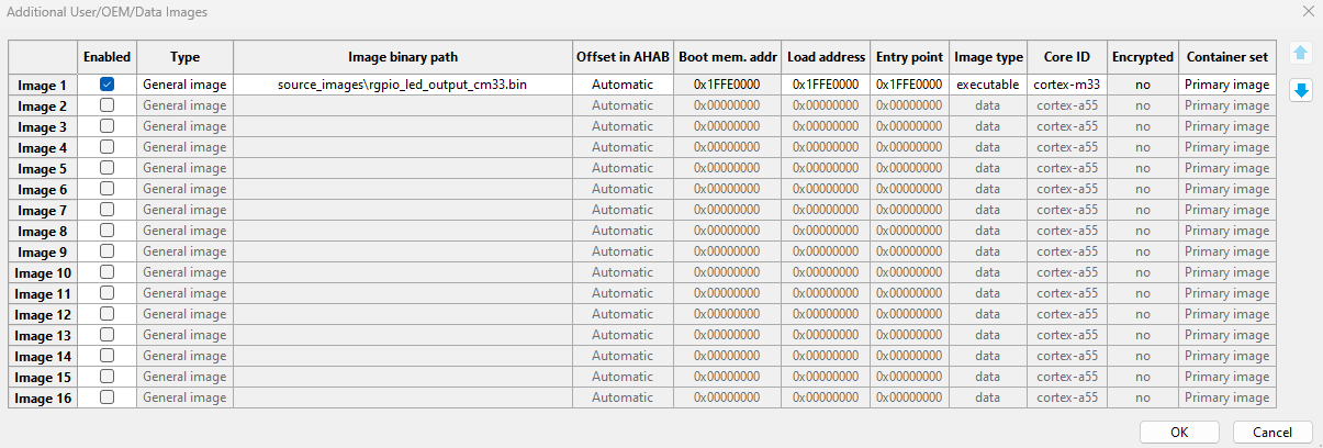
Fig. 50 Bootloader images for Container set with Cortex-M33 application#
A container set with Cortex-A55 U-Boot (bootloader). It is written to the eMMC/SD card by the nxpuuu utility during write. During the boot, this bootloader is used to boot the Linux kernel image.

Fig. 51 Bootloader images for Container set with Cortex-A55 U-Boot#
i.MX 95 bootable image examples#
A container set with the Cortex-M7 application. It is written to on-chip RAM by the nxpuuu utility during write and then started from there.
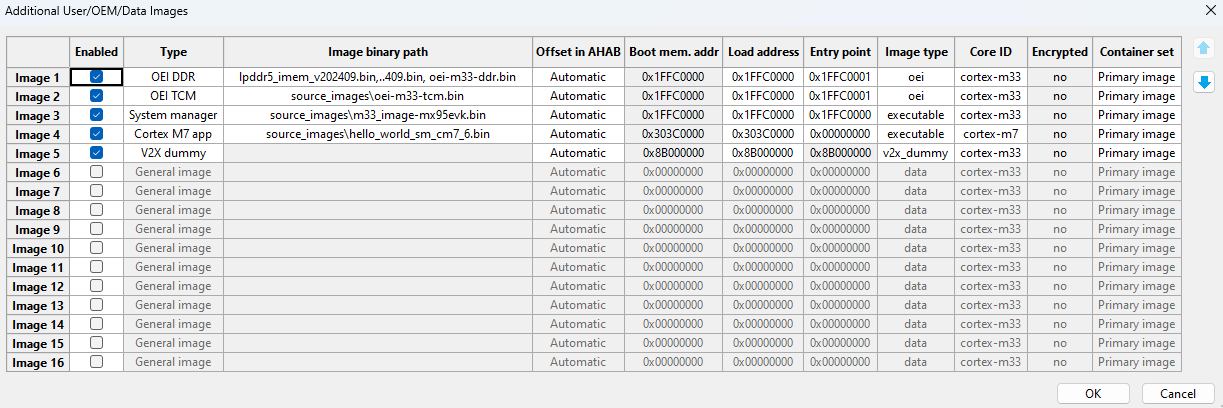
Fig. 52 Bootloader images for Container set with Cortex-M7 application#
A container set with Cortex-A55 U-Boot (bootloader). It is written to the eMMC/SD card by the nxpuuu utility during write. During the boot, this bootloader is used to boot the Linux kernel image.

Fig. 53 Bootloader images for Container set with Cortex-A55 U-Boot#
Booting/loading unsigned image#
First, build a bootable image:
Select the Unsigned boot type in the Toolbar.
Select boot device in the Toolbar.
Switch to the Build image
Open the Bootloader images dialog by clicking the Bootloader images button.
Configure the images for the image container, see i.MX 93 bootable image examples or i.MX 95 bootable image examples. Select the prepared images from Preparing images for build for i.MX 9x devices.
Enable the image in the Enabled column.
Select the image entry using Type
Select the binary(s) in the Image binary path.
Select Container set, it should be either Primary image or Secondary image.
All other parameters are preset with default values for the selected image entry type. These parameters can be customized.
Close the dialog by clicking the OK button.
Click the Build image button to build a bootable image,
flash.bin.
When the bootable image has been successfully built:
Make sure that the board is in Serial bootloader ISP mode.
Switch to the Write image view.
Click the Write image button.
The nxpuuu utility is used to load the bootable image to the device.
If the write operation was successful:
For eMMC or SD card, switch boot mode (see Table 8. Boot mode selection for board for i.MX 9x Cortex-M33 core or Table 9. Boot mode selection for board for i.MX 9x Cortex-A55 core ) and reset the board. The applications shall run:
hello_worldin Cortex-M7 and/or U-Boot in Cortex-A55.For Serial downloader, the Cortex-M7/Cortex-M33 application runs after it is written.
Booting signed bootloader image from Cortex-M33 or Cortex-A55#
This section describes the building and writing of a signed image - either for booting from Cortex‑A55 on i.MX 93 or from Cortex‑M33 on i.MX 95. Keys generated in the PKI management view are needed in this step. For more information about generating keys, see Generate keys.
First, build a bootable image (bootloader for Cortex-A55):
In the Toolbar set Boot type to Signed.
Select boot device in the Toolbar.
Switch to the Build image
Open the Bootloader images dialog and configure the images for the bootloader. See the example for container set with Cortex-A55 U-Boot (bootloader) in i.MX 93 bootable image examples or i.MX 95 bootable image examples and Build U-Boot with AHAB secure boot features.
For Authentication key select any key, for example, SRK1.
Select the OEM Open or OEM Closed life cycle. See chapter Get ELE events with nxpele utility how to verify the application in the OEM Open life cycle.
Click the Build image button.
Check that the bootable image was built successfully.
When the bootable image has been successfully built:
Make sure that the board is in Serial bootloader ISP mode.
Switch to the Write image view.
Make sure that the Use built image checkbox is selected. This will write the built bootloader to the selected boot device.
Note: To write another prepared bootable image, another bootloader or a complete image with Linux kernel, unselect the checkbox and select your image. The bootloader built on Build image is still used during write to write fuses and to update the life cycle with the nxpele utility.
Click the Write image button.
The nxpuuu utility is used to load the bootloader, with U-Boot, to RAM.
The nxpele utility is used to write fuses and to update life cycle.
The nxpuuu utility is used to load the bootloader/your prepared bootable image to the boot device.
In the following window, confirm to write fuses and update the life cycle:
OK - Continue writing the image and burning fuses.
Cancel - Abort writing the image and burning fuses.
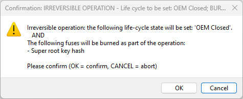
Fig. 54 Burn fuses on i.MX 93#
If the write operation was successful, switch the boot mode (see Table 8. Boot mode selection for board for i.MX 9x Cortex-M33 core or Table 9. Boot mode selection for board for i.MX 9x Cortex-A55 core in) and reset the board. The applications shall run U-Boot/your prepared bootable image in Cortex-A55.
Write fuses and update life cycle with nxpele over U-Boot#
The nxpele utility is used during provisioning to write fuses or to update life cycle. It is also used to read fuses in the OTP Configuration dialog. The nxpele utility communicates with EdgeLock Enclave over U-Boot, which must be running on the target.
In these cases, the bootable image configured in the Bootloader images dialog is used as a bootloader with the U-Boot. The U-Boot must be built with AHAB features, see Build U-Boot with AHAB secure boot features for details. During the device provisioning, the bootloader is loaded to the target and started.
Life cycle for i.MX 9x devices#
In the current tool version, there is a limitation when advancing the life cycle on clean i.MX 9x devices. The life cycle must be advanced in separate steps:
Perform the Booting signed bootloader image from Cortex-M33 or Cortex-A55 while selecting the OEM Open life cycle. During this step, the SRK fuses are programmed.
Keep the board in Serial bootloader (ISP) mode and reset the board.
Select the OEM Closed life cycle and do build and write again. For i.MX 93 devices, the life cycle can be advanced directly to OEM Locked at this step.
For i.MX 95 devices, if the OEM Locked life cycle is needed, keep the board in Serial bootloader (ISP) mode and reset the board. Otherwise, proceed to step 6.
Select the OEM Locked life cycle and do build and write again.
Switch the boot mode (see Table 8. Boot mode selection for board for i.MX 9x Cortex-M33 core or Table 9. Boot mode selection for board for i.MX 9x Cortex-A55 core in) and reset the board. The applications shall run U-Boot/your prepared bootable image in the selected life cycle.
Build U-Boot with AHAB secure boot features#
The U-Boot/SPL nxp-imx/uboot-imx provides extra secure boot features. The features enable the nxpele utility to communicate with EdgeLock Enclave. The support is enabled by setting CONFIG_AHAB_BOOT=y in the build.
If the nxpele utility over fastboot is used, multiplexing of the console output to fastboot must be enabled by setting CONFIG_CONSOLE_MUX=y.
Get ELE events with nxpele utility#
The nxpele get-event command can retrieve stored events in EdgeLock Enclave. The nxpele utility communicates with ELE over U-Boot, which must be running on the target.
Thanks to this, we can, for example, check the container authentication status in the OEM Open life cycle:
See Booting signed bootloader image from Cortex-M33 or Cortex-A55. In this procedure, keep the life cycle in OEM Open. In the OEM Open life cycle, the authentication result is ignored.
Connect the DBG port to your PC.
Switch to boot mode and reset the board.
Check what serial COM port is the U-Boot console output.
Close the serial connection session if opened in a terminal.
Execute
nxpele get-events
Example when authentication succeeds:
C:\nxp\SEC_Provi_25.09\bin\_internal\tools\spsdk>nxpele -f mimx9352 -p COM21 get-events
ELE get events ends successfully.
Event count:     0
Example when authentication fails:
C:\nxp\SEC_Provi_25.09\bin\_internal\tools\spsdk>nxpele -f mimx9352 -p COM21 get-events
ELE get events ends successfully.
Event count:     2
Event[0]:      0x0287FAD6
  IPC ID:        Application Processor message unit
  Command:       OEM Container authenticate
  Indication:    The key hash verification does not match OTP
  Status:        The request was successful
Event[1]:      0x0287FAD6
  IPC ID:        Application Processor message unit
  Command:       OEM Container authenticate
  Indication:    The key hash verification does not match OTP
  Status:        The request was successful
KW45xx/K32W1xx/MCXW71xx/KW47xx/MCXW72xx device workflow#
This chapter describes workflow for KW45xx/K32W1xx/MCXW71xx/KW47xx/MCXW72xx processors.
Preparing source image for KW45xx/K32W1xx/MCXW71xx/KW47xx/MCXW72xx devices#
In this step, select the target memory where the image is executed. The following options are available for KW45xx/K32W1xx/MCXW71xx/KW47xx/MCXW72xx devices:
Image running from an internal flash (XIP image)
There is no need to modify the default configuration, build the MCUXpresso SDK example as it is.
Connecting the board for KW45xx/K32W1xx/MCXW71xx/KW47xx/MCXW72xx devices#
This section contains information about configuring the following evaluation boards and connecting them to SEC Tool:
KW45B41Z-EVK
K32W148-EVK
MCXW71-FRDM
MCXW71-EVK
KW47-EVK
It is assumed that the SEC Tool is already running with a workspace created for an KW45xx/K32W1xx/MCXW71xx/KW47xx/MCXW72xx device. For more information, see Setting up Secure Provisioning Tool.
For the KW45B41Z-EVK and K32W148-EVK development boards:
Connect the J14 port to your PC with a USB cable.
Set the JP25 jumper to enable the SW4 button.
Enable the ISP boot mode by holding the SW4 button and reset.
In the Connection dialog, test the connection to the processor.
For the MCXW71-FRDM development board:
Connect the J10 port to your PC with a USB cable.
Enable the ISP boot mode by holding the SW3 button and reset.
In the Connection dialog, test the connection to the processor.
For the MCXW71-EVK development board:
Connect the J14 port to your PC with a USB cable.
Enable the ISP boot mode by holding the SW4 button and reset.
In the Connection dialog, test the connection to the processor.
For the KW47-EVK development board:
Connect the J14 port to your PC with a USB cable.
Enable the ISP boot mode by holding the SW4 button and reset.
In the Connection dialog, test the connection to the processor.
Booting images for KW45xx/K32W1xx/MCXW71xx/KW47xx/MCXW72xx devices#
This section describes the building and writing of bootable images. For KW45xx/K32W1xx/MCXW71xx/KW47xx/MCXW72xx, the SEC Tool supports XIP images only.
Booting plain or CRC image#
Plain images are typically used for development. Start with this boot type before working with secured images to verify that the executable image works properly. Dual image boot is supported only for secure boot types.
First, build a bootable image:
Make sure that you have selected the Plain unsigned or Plain with CRC boot type is selected in the toolbar.
Switch to the Build image view.
Select an application image built in Building example project as a Source executable image.
If there is a binary image, set the start address to 0x0.
Click the Build image button to build a bootable image. The result is a binary bootable image.
When the bootable image is built, upload it to the processor:
Make sure that the processor is in ISP mode.
Switch to the Write image view.
Click the Write image button.
If the write operation was successful, reset the board.
Booting signed image#
This section describes building and writing a signed image.
Build a bootable image:
Select the Plain signed boot type in the toolbar.
Switch to the Build image view.
Select an application image built in Building example project as a Source executable image.
Ensure that you have the keys on the PKI management tab. Evaluation boards KW45B41Z-EVK, K32W148-EVK, MCXW71-FRDM, and KW47-EVK are produced with preprogrammed ROKTH and SB3KDK keys in the fuses
CUST_PROD_OEMFW_AUTH_PUKandCUST_PROD_OEMFW_ENC_SK. These keys are also distributed in the SEC Tool and can be imported from the tool foldersample_data\targets\<processor>\board_example_keys. See Import/Export keys. These keys are intended for evaluation purposes only and must not be used for production.For Authentication key select any key, for example ROT1: IMG1_1
Use an imported value or create your own (random) one for SB3KDK symmetric key.
If needed, open Dual image boot and configure. Image must be linked to the Flash Logical Window.
Keep OEM Open in the life cycle.
Click the Build image button to build a bootable image. The result is an SB3 capsule for installation into the processor.
When the bootable image and SB3 capsule have been successfully built, you can upload to the processor:
Make sure that the processor is in ISP mode.
Switch to the Write image view.
Keep OEM Open in the life cycle.
Make sure that the IFR fields written in otp_config.sb are not burned already. All IFR fields are one time programmable.
Click the Write image button.
Note: If IFR fields are written in the otp_config.sb, it is not possible to receive otp_config.sb multiple times.
Booting PRINCE encrypted image#
Encrypted unsigned images, images with CRC or signed images are supported. The process of creating an encrypted image is similar to a signed image. In addition, configure encrypted regions in the Build image view. Use the PRINCE regions button to configure encrypted regions. In combination with the dual boot, set one region for image0 and one for image1. Setting a region only for image0 does not encrypt image1.
Image encryption is performed when the image is written to the target memory.
The regions configuration is included into the ROMCFG page.
Note: Open OTP/IFR configuration to review the PRINCE settings in the ROMCFG block(s) as the block must be specified and can be written only once. It is an irreversible operation.
Life cycle for KW45xx/K32W1xx/MCXW71xx/KW47xx/MCXW72xx devices#
The default life cycle, which should be used for development, is OEM Open. Before you deploy the application, set the OEM Closed or OEM Locked life cycle (see documentation for the target processor for detailed description).
Note: Change of the life cycle is irreversible.
Once the processor is in “OEM Closed” or “OEM Locked” mode, the tool does not allow initializing the ROMCFG page. The application can still be updated via the SB file.
OEM OPEN |
OEM CLOSED/LOCKED |
|
|---|---|---|
Plain unsigned or CRC boot type |
- Only user fuses burnt |
- life cycle fuse burnt |
Plain signed boot type |
- RKTH and SB3KDK burnt in write script |
- RKTH and SB3KDK burnt in write script |
Encrypted boot type |
- RKTH and SB3KDK burnt in write script |
- RKTH and SB3KDK burnt in write script |
Open life cycle, no trust provisioning |
Closed life cycle, no trust provisioning |
Open life cycle, EdgeLock 2GO |
Closed life cycle, EdgeLock 2GO |
|
|---|---|---|---|---|
SB3KDK |
Write script |
Write script |
sb3kdk.asc |
sb3kdk.asc |
RKTH fuses |
Write script |
Write script |
rkth.bin |
rkth.bin |
Other custom fuses and IFR |
Write script or otp_config.sb |
otp_config.sb |
otp_config.sb |
otp_config.sb |
EdgeLock 2GO#
EdgeLock 2GO is described in EdgeLock 2GO trust provisioning workflow. Below are KW45xx/K32W1xx/MCXW71xx/KW47xx/MCXW72xx specific comments:
The life cycle is set to the life cycle set to the secure objects. The RKTH and SB3KDK fuses are always burned during provisioning, even in the development life cycle.
Address for secure objects must be in internal flash, provisioning firmware erases the area before writing the secure objects.
For KW47 and MCXW72, the OEM_SEC_BOOT_EN fuse is burned by the provisioning firmware if the secure object is set to either “OEM Closed” or “OEM Locked” life cycle.
NXP keys for KW45xx/K32W1xx/MCXW71xx boards#
Some EVK and FRDM boards are pre-programmed with NXP keys. Therefore, any signed scenario must use these keys. In the SEC Tool, the keys are distributed in the following folder: data\sample_data\targets\<processor>\board_example_keys. It is possible to import the keys using the Import keys function in the PKI management tab. Alternatively, you can create a workspace with these keys by selecting a profile that includes board keys in its name, for example: Plain signed image running on on-chip flash — KW45B41Z-EVK keys.
Update NBU firmware#
This feature is available only for processors with radio. The NBU firmware is distributed within the MCUXpresso SDK as an SB3 file, as an NXP-signed binary file (*.xip) or as a binary file (*.bin), in folder middleware\wireless\ble_controller\bin.
The NBU firmware can be updated via an SB file. This chapter describes the step-by-step process of:
how to create an SB file using custom keys.
how to use an SB file from the MCUXpresso SDK on the EVK/FRDM boards with NXP keys,
how to create an SB file using custom keys with a custom-signed NBU firmware.
Note: SDK Bluetooth examples for KW47xx boot only once when signed. This issue is caused by the example application, which erases a flash region during execution for future use. However, the erased region contains the signature required for subsequent boots.
Update NBU firmware using custom SB file#
Open a workspace for KW45xx/K32W1xx/MCXW71xx/KW47xx/MCXW72xx with the custom keys that were provisioned to the device.
Copy the NBU firmware (xip or bin image from SDK) into the workspace as
source_images\nbu_firmware.xipIn the menu bar, select Tools > SB Editor.
Fill the Properties tab or import a setting from the SB file created on the Build tab.
Switch to the Commands tab.
Select high-level command update-nbu-firmware
Prepare the final SB file by clicking the Generate button.
Click the To Manufacturing tool button to switch to the manufacturing window with the preselected Apply SB file operation and the preselected SB file.
Detect a connected device by clicking the Auto detect button.
Load the SB file by clicking the Start button.
Update NBU firmware using SB file with NXP keys on KW45xx/K32W1xx/MCXW71xx devices#
Note: The following steps apply only to boards manufactured with NXP keys. See NXP keys for KW45xx/K32W1xx/MCXW71xx boards.
Create a new workspace with the NXP keys as described in NXP keys for KW45xx/K32W1xx/MCXW71xx boards.
In the menu bar, select Tools > Manufacturing Tool.
Select the Apply SB file operation.
Provide the SB file.
Detect a connected device by clicking the Auto detect button.
Load the SB file by clicking the Start button.
Update signed NBU firmware using custom SB file on KW47xx/MCXW72xx devices#
Note: Ensure that the OTP fuse NBU_SEC_BOOT_EN is set to enable verification of the NBU signature during boot.
Open a workspace for KW47xx/MCXW72xx configured with the custom keys provisioned on the device.
Create a copy of
configs/mbi_config.yaml, for exampleconfigs/mbi_config_nbu.yamlIn the new configuration file, modify the following parameters:
Set
inputImageFileto the path of the NBU firmware .bin.Set
masterBootOutputFileto../source_images/nbu_firmware.xipSet
outputImageAuthenticationTypetonbu-signed
Build the signed image by executing:
nxpimage mbi export -c configs\mbi_config_nbu.yamlIn the menu bar, select Tools > SB Editor.
Fill in the Properties tab, or import a setting from the SB file created on the Build tab.
Switch to the Commands tab.
Select high-level command update-nbu-firmware
Generate the final SB file by clicking the Generate button.
Click the To Manufacturing tool button to switch to the manufacturing window with Apply SB file preselected, along with the generated SB file.
Detect a connected device by clicking the Auto detect button.
Load the SB file by clicking the Start button.
LPC55(S)0x/1x/2x/6x or NHS52Sxx or MCXW23x device workflow#
This chapter describes workflow for LPC55(S)0x/1x/2x/6x, NHS52S04, and MCXW236 processors.
Preparing source image for LPC55(S)0x/1x/2x/6x devices#
In this step, you must select the target memory where the image is executed. The following option is available for LPC55Sxx devices:
Image running from an internal flash (XIP image)
Image running from internal flash#
MCUXpresso IDE
Build the project.
Open the debug folder.
Right-click the named <your.project>.axf file.
Select Binary Utilities > Create binary.
IAR
In Project > Options > Output Converter, check Generate additional output and select Raw binary output format.
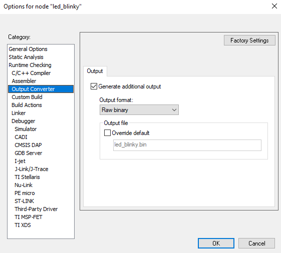
Fig. 55 IAR options#
Build the project. You find the output image built as
boards\\lpc55s\#\#\\demo\_apps\\led\_blinky\\iar\\led\_blinky\\led\_blinky.bin.
Keil MDK 5
In Project > Options > User > After Build/Rebuild, check the Run #1 option.
Enter the following in the User Command path (where myprog is the project’s Name of Executable):
C:\Keil\ARM\ARMCC\bin\fromelf.exe --bin --output=myprog.bin myprog.axf.Build the image. You find the output image built as
boards\lpc55s\#\#\\demo\_apps\led\_blinky\mdk\led\_blinky\led\_blinky.bin.
Connecting the board for LPC55(S)0x/1x/2x/6x devices#
This section contains information about configuring the following LPC5Sxx evaluation boards and connecting them to SEC:
LPCexpresso55S69
LPCexpresso55S66
LPCexpresso55S28
LPCexpresso55S26
LPCexpresso55S16
LPCexpresso55S14
LPCexpresso55S06
LPCexpresso55S04
NHS52Sxx-EVK
FRDM-MCXW236B
It is assumed that the SEC Tool is already running with a workspace created for an LPC device. For more information, see Setting up Secure Provisioning Tool.
To communicate via UART, connect USB cable to P6 connector, for USB communication use P9 connector.
On FRDM-MCXW236B set jumpers JP13 and JP14 to position 2-3 instead of 1-2.
Enable the ISP boot mode by holding the ISP button and reset.
Ensure that you have selected the Unsigned boot type in the Toolbar.
In the Connection dialog, set the connection to USB or UART according to the selected port and test the connection to the processor.
Booting images for LPC55(S)0x/1x/2x/6x devices#
This section describes the building and writing of images.
Security levels#
The following security levels are supported in the SEC Tool:
Unsigned boot types : Default processor configuration that does not provide any security. It is recommended to start with the unsigned boot type to ensure the bootable image works on the processor. Unsigned boot types are intended for development only.
Signed or encrypted boot types - unsealed : Unsealed boot types are also designed to be used during development to ensure the selected boot type works well. In the KeyStore, CFPA, and CMPA pages are written into the processor. CMPA page is not sealed and can be updated or erased.
Signed or encrypted boot types - sealed : A sealed CMPA page is recommended for production. Select the Deployment life cycle in the Write image view to seal the CMPA page. Once sealed, it cannot be changed or erased.
Booting Plain/Plain with CRC image#
This section describes the building and writing of plain/plain with CRC image.
In the Toolbar, set Boot Type to Plain unsigned or Plain with CRC.
As a Source executable image, use the image from Preparing source image for LPC55(S)0x/1x/2x/6x devices as a Source executable image.
In the case of a binary image, set the start address to 0x0.
If needed, open Dual image boot and configure.
Click the Build image button.
Check that the bootable image was built successfully.
Once the image has been successfully built, do the following:
Make sure that the board is in ISP mode.
Click the Write image view.
Click the Write image button.
If the write operation was successful, reset the board.
Booting plain signed or PRINCE encrypted image#
This section describes the building and writing of an authenticated or PRINCE encrypted image. Keys generated in the PKI management view are needed in this step. For more information about generating keys, see Generate keys.
Note: The keys are also used for Encrypted (PRINCE) Plain and with CRC boot type because the bootable image is updated using SB capsule, which must be signed.
In the Toolbar, set Boot type to Plain signed, Encrypted (PRINCE) unsigned, Encrypted (PRINCE) with CRC, or Encrypted (PRINCE) signed.
In the Build image view, use the image from Preparing source image for LPC55(S)0x/1x/2x/6x devices as a source executable image.
For Authentication key, select any keychain, for example, ROT1: IMG1_1_1.
Open the PRINCE configuration and check the configuration. Set the size of the PRINCE region based on the size of the bootable image.
If needed, open Dual image boot and configure. For a PRINCE encrypted image, set one region for image0 and one for image1. Setting a region only for image0 does not encrypt image1.
Click the Build image button.
Check that the bootable image was built successfully.
To write the image, do the following:
Select the Write image view.
Make sure that the board is connected and the ISP mode is enabled (See Connecting the board for LPC55(S)0x/1x/2x/6x devices )
Click the Write image button.
If the write operation was successful, reset the board.
Once the image can be successfully executed in the processor, select the Deployment life cycle to permanently seal the device security with sha256 signature of the CMPA page. If the option remains unselected the security can be reconfigured. After you select the Deployment life cycle, click the Build image button in the Build image view. Then click the Write image button again and confirm the following message box:
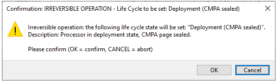
Fig. 56 Confirm write#
If the write operation was successful, reset the board.
Note: It is necessary to completely erase the entire processor before returning from PRINCE encryption to a non-encrypted image.
PFR and PUF KeyStore#
This section provides information about PFR and PUF KeyStore.
PUF KeyStore initialization
SEC initializes KeyStore on LPC55Sxx devices only once in the device life cycle.
KeyStore enrollment status for the device is reported in the Connection dialog, using the Test button.
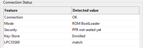
Fig. 57 KeyStore connection#
It is possible to update the keys in the KeyStore, so it should not be needed to re-initialize KeyStore. In case of unexpected troubles, you can try to erase KeyStore, however, it is not recommended. With the KeyStore, it is recommended to also clear the CFPA page, as PRINCE IV fields in CFPA depend on the KeyStore. The device does not boot if you enroll the KeyStore and try to use it with previous IV fields.
How to erase KeyStore (example for LPC55S69)
bin/tools/blhost/win/blhost -u 0x1FC9,0x0021 -j -- set-property 29 1

bin/tools/blhost/win/blhost -u 0x1FC9,0x0021 -j -- write-memory 0x9E600 zero_1536.bin
zero_1536.bin is a file that contains zeros, and the file size is 3*512 bytes.
How to update CFPA page (example for LPC55S69)
Increment the version in
cfpa.json: it is recommended to add at least 0x10 from the last known version as the version is also incremented during PRINCE IV updates.Run the following commands to update the CFPA page into the processor:
bin/tools/spsdk/pfr generate -c cfpa.json -o cfpa.bin
bin/tools/spsdk/blhost -u 0x1FC9,0x0021 -j -- write-memory 0x0009DE00 cfpa.bin
DCFG_CC_SOCU problem on LPC55Sxx
LPC55S0x/1x/2x/6x processors do not support the DCFG_CC_SOCU field configured in CFPA, while DCFG_CC_SOCU in CMPA is zero (not configured yet) and the processor may stop work (lock) if the configuration happens. It is recommended to always configure CMPA first and erase CFPA (+reset) in case erasing of CMPA is needed.
LPC55(S)3x device workflow#
Preparing source image for LPC55(S)3x devices#
In this step, select the target memory where the image is executed. The following options are available for LPC55(S)3x devices:
Image running from internal FLASH - XIP (eXecution In Place) image, which means that the image is executed directly from the memory where it is located.
It is the default option for almost all SDK examples. There is no need to modify the default configuration, build the example as it is.
Image running from external FLASH - XIP (eXecution In Place) image, which means that the image is executed directly from the memory where it is located.
The image must start at address 0x8001000. The other locations are not supported now. There is no need to modify the default configuration.
For custom external FLASH, the configuration of external FLASH for booting can be adjusted in CMPA.
Connecting the board for LPC55(S)3x devices#
This section contains information about configuring the evaluation board LPC55S36-EVK and connecting it to SEC.
Select ISP boot mode, see Table 12. Boot mode selection for LPC55S36 EVK board below.
Connect the J3 port to your PC with a USB cable.
Ensure SEC runs with a workspace created for the chosen device. For more information, see Setting up Secure Provisioning Tool.
Make sure that the boot memory in the toolbar matches NOR FLASH used on EVK board (for example, flex-spi-nor/ISxxxx) or internal flash.
Set the connection to USB and test the board connection.
Board |
ISP mode |
Boot from internal FLASH |
Boot from external FLASH |
|---|---|---|---|
LPC55S36-EVK |
J43: 1-2 open, 3-4 closed |
J43: 1-2 closed, 3-4 closed |
J43: 1-2 closed, 3-4 open |
Booting images for LPC55(S)3x devices#
This section describes the building and writing of bootable images. For LPC55S3x, the SEC Tool supports XIP images only.
Booting plain unsigned or CRC image#
A plain image is typically used for development. Start with this boot type before working with secured images to verify that the executable image works properly.
First, build a bootable image:
Make sure that you have selected the Plain unsigned or Plain with CRC boot type in the toolbar.
Switch to the Build image view.
Select image built in Preparing source image for LPC55(S)3x devices as a Source executable image.
If there is a binary image, set the start address to 0x0 for internal flash, or 0x8001000 for external flash.
If needed, open Dual image boot and configure.
Click the Build image button to build a bootable image. The result is a binary bootable image.
When the bootable image is built, upload it to the processor:
Make sure that the processor is in ISP mode.
Switch to the Write image view.
Click the Write image button.
If the write operation is successful, switch boot mode (see Table 12. Boot mode selection for LPC55S36 EVK board ) and reset the board.
Booting plain signed image#
This section describes building and writing a plain signed image.
Build a bootable image:
Select the Plain signed boot type in the toolbar.
Switch to the Build image view.
Select image built in Preparing source image for LPC55(S)3x devices as a Source executable image.
For Authentication key select any key, for example ROT1: IMG1_1
Use random value for “CUST_MK_SK” and “OEM seed” symmetric keys.
If needed, open Dual image boot and configure.
Open the PFR configuration and on the CMPA page check, that the bit-field
SEC_BOOT_ENin theSECURE_BOOT_CFGfield is configured. It is necessary to select any type of image check.Make sure that the board is connected and the processor is in ISP mode. During building processes, provisioning SB file for installation of
CUST_MK_SKinto processor is prepared.Note: The processor is reset after the SB file is built.
Keep Develop in life cycle
Click the Build image button to build a bootable image. The result is a binary bootable image and SB3 capsule for installation of the image into the processor.
When the bootable image has been successfully built, you can upload to the processor:
Make sure that the processor is in ISP mode.
Switch to the Write image view.
Click the Write image button.
Booting encrypted image#
Encrypted images with CRC or signed images are supported. The process of creation an encrypted image is similar to a signed image. In addition, configure encrypted regions in the Build image view:
Use the PRINCE Regions button to configure encrypted regions for internal FLASH
Use the IPED Regions button to configure encrypted regions for external FLASH
In both cases, the whole image is encrypted by default. For clock limitations when using encrypted images, see documentation for the target processor. With the dual boot, set one region for image0 and one for image1. Setting a region only for image0 does not encrypt image1.
Image encryption is performed when the image is written to the target memory. The encrypted region is configured in the SB file. The decrypted regions are configured in the CMPA page, so make sure these two are aligned.
Test life cycle#
To test processor behavior in the advanced life cycle, it is possible to temporarily change the life cycle to some higher level by setting control register PMC->LIFECYCLESTATE to the required level. This life-cycle state is valid until HW is reset.
Required steps:
Prepare the image and generate keys.
Set access control in SOCU registers.
Build the image
Execute write operation.
Run the application.
Connect a debug probe.
On the write tab, click the Test life cycle button and in the displayed dialog set the required life cycle state.
Click Apply to move the processor into the selected life cycle. Now, it is possible to test the processor behavior.
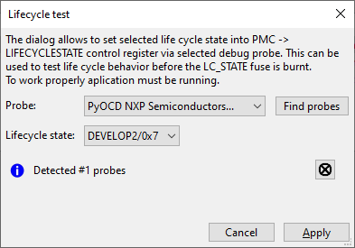
Fig. 58 Lifecycle test#
Life cycle for LPC55(S)3x devices#
The default life cycle, which should be used for development, is Develop. Before you deploy the application, set the “In Field” or “In Field Locked” life cycle (see documentation for the target processor for detailed description).
Note: Change of the life cycle is irreversible.
When changing to In Field life cycle, CMPA and CFPA pages are installed in the dev_hsm_provi.sb file. It is supposed that in this mode, the pages are installed into an empty processor, so there are not any failures (the page update may fail, so in development mode, these pages are updated in write script, where the progress and error report are much better). Once the processor is in In Field state, the SEC Tool supports only update of the application image; updates of CMPA and CFPA are not supported.
LPC865 workflow#
This section describes the LPC865 device workflow in detail.
Preparing images for build for LPC865#
The processor supports only images executed from internal flash (XIP). Use the default toolchain settings to build the application image.
Connecting the LPCXpresso860-MAX board for LPC865#
This section contains information about configuring the evaluation board LPCXpresso860-MAX and connecting it to the SEC Tool.
To power the board, connect the J4 USB port with the USB cable to your power adapter or PC.
Connect pins 2(RX) and 4(TX) at the J2 connector to the UART converter and connect to your PC.
To switch the processor into ISP mode, hold the ISP(SW1) button and press RESET(SW3).
Ensure that the SEC Tool is already running with a workspace created for the chosen device. For more information, see Setting up Secure Provisioning Tool.
Open the Connection dialog and test the board connection. Mind the first board synchronization take a longer time.
Booting images for LPC865#
This chapter describes the building and writing of plain bootable image.
Booting unsigned plain image#
Plain unsigned is the only boot mode supported by this processor.
First, build a bootable image:
Switch to the Build image view.
Select an image built in Preparing source image for MC56F818xx/7xx/6xx and MWCT2xD2/12 devices as a Source executable image.
If there is a binary image, set the start address to 0x0.
Click the Build image button to build a bootable image. During this operation, the following changes are applied to the image: life cycle (=code read protection) and CRC.
When the bootable image is built, upload it to the processor:
Make sure that the processor is in ISP mode.
Switch to the Write image view.
Click the Write image button.
If the write operation is successful, reset the board. The processor will boot after several seconds.
Life cycles#
The processor does not support real-life cycles, so the code read protection can be configured instead of life cycle.
MC56F818xx/7xx/6xx and MWCT2xD2/12 devices workflow#
This chapter describes workflow for MC56F818xx/7xx/6xx and MWCT2xD2/12 processors.
Preparing source image for MC56F818xx/7xx/6xx and MWCT2xD2/12 devices#
In this step, select the target memory where the image is executed. The following options are available for MC56F818xx/7xx/6xx and MWCT2xD2/12 devices:
Image running from an internal flash - XIP (eXecution In Place) image, which means that the image is executed directly from the internal flash memory. There is no need to modify the default configuration, build the MCUXpresso SDK example as it is.
Connecting the board for MC56F818xx/7xx/6xx and MWCT2xD2/12 devices#
This section contains information about configuring the evaluation boards and connecting it to SEC:
MC56F81868-EVK
MC56F81000-EVK
WCT-QI2
Power the board from USB_TYPE_C port (WCT-QI2).
Connect the J4 1-TX, 3-RX, 5-GND port (WCT-QI2) via the MCU-Link to your PC.
In the Connection dialog, set the connection to UART
To get to ISP boot mode, send a blhost command to the processor within 5 seconds after the board startup, for example click the Test connection button in the Connection dialog.
Note: The processor boots from internal flash when there is no blhost command sent within 5 seconds after the startup.
Booting images for MC56F818xx/7xx/6xx and MWCT2xD2/12 devices#
This chapter describes the building and writing of plain and signed bootable images.
Booting plain unsigned or CRC image#
Plain images are typically used for development. Start with this boot type before working with secured images to verify that the executable image works properly.
First, build a bootable image:
Make sure that you have selected the Plain unsigned or Plain with CRC boot type in the toolbar.
Switch to the Build image view.
Select an image built in Preparing source image for MC56F818xx/7xx/6xx and MWCT2xD2/12 devices as a Source executable image.
If there is a binary image, set the start address to 0x0.
If needed, open BCA/FCF configure.
Click the Build image button to build a bootable image. The result is a binary bootable image. For secure processors there are also separated boot headers binary (BCA, FCF) and binary with application. This is due to the DUKB area in the internal flash that must stay untouched during the write.
When the bootable image is built, upload it to the processor:
Make sure that the processor is in ISP mode.
Switch to the Write image view.
Click the Write image button.
If the write operation is successful, reset the board. The processor will boot after 5 seconds.
Booting plain signed image#
This section describes building and writing a plain signed image.
Build a bootable image:
Select the Plain signed boot type in the toolbar.
Switch to the Build image view.
Select an image built in Preparing source image for MC56F818xx/7xx/6xx and MWCT2xD2/12 devices as a Source executable image.
For Authentication key, select ROT1.
Make sure that the board is connected and the processor is in ISP mode. During building processes, an SBx file is prepared. The processor is used as HSM to create an encrypted SBx file.
Keep OEM Open in the life cycle. See Life cycle and device HSM trust provisioning for MC56F818xx/7xx/6xx and MWCT2xD2/12 devices for OEM Closed life cycle.
Click the Build image button to build a bootable image. The result is a binary bootable image, boot headers binary (BCA, FCF), and SBx capsule for installation of the image into the processor.
When the bootable image has been successfully built, you can upload to the processor:
Make sure that the processor is in ISP mode.
Switch to the Write image view.
Click the Write image button.
Life cycle and device HSM trust provisioning for MC56F818xx/7xx/6xx and MWCT2xD2/12 devices#
The default life cycle used for development is OEM Open. Before you deploy the application, set the OEM Closed life cycle (see documentation for the target processor for a detailed description).
When the OEM Closed life cycle and Device HSM are set in the toolbar, the trust provisioning SBx file is created during the build. The IFR ISK_CERT_HASH fields are written to IFR by the dev_hsm_provi.sbx file. It is supposed that in this mode, the IFR fields have default values in the processor.
Warning:
Writing of IFR fields is irreversible.
WPC provisioning must be done before advancing the life cycle. Once the board was moved into the advanced life cycle, the provisioning command is not available.
It is possible to reset the life cycle into an OEM Open state if needed. There are two possibilities:
Keep the Plain signed boot type, set the OEM Open life cycle, disable trust provisioning and do build and write. With this, the application is updated and the life cycle is set to OEM Open. Fields in IFR remain unchanged.
Set Plain unsigned boot type, OEM Open life cycle, disable trust provisioning and do build and write. For some devices, it may be necessary to disable flash security before executing the write operation (to enable the FlashEraseAllUnsecure command). With this, the entire flash memory is erased and the life cycle is set to OEM Open. Fields in IFR remain unchanged.
The blhost flash-erase-all command erases the entire memory, which also affects the life cycle state. After flash-erase-all and device reset, the life cycle is in the Closed state.
ISK_CERT_HASH |
SBx file |
|
|---|---|---|
OEM Open lifecycle, Signed boot type |
Included in FCB |
SBx used to write/update the application image |
OEM Closed life cycle, Signed boot type |
Irreversibly written to IFR in trust provisioning SBx file |
SBx used to write/update the application image |
EdgeLock 2GO WPC workflow#
The EdgeLock 2GO platform provides provisioning of the Wireless Power Consortium (WPC) Certificate chain needed for WPC Qi authentication. The SEC Tool supports a WPC provisioning scenario where NXP serves as WPC Manufacturing CA Service Provider. For the workflow, it is supposed that the NXP example project is used. Contact NXP sales to get the example.
EdgeLock 2GO WPC flow, step by step#
To configure WPC Certificate provisioning, do the following steps:
Turn on secure boot mode and verify that the application works properly.
On the EdgeLock 2GO server, create Qi Manufacturer CAs and Product Unit Certificates
Create an API key. For details, see the API key to access the EdgeLock 2GO server.
In the main menu > Target > Trust Provisioning Mode, check the enable WPC and fill the EdgeLock2GO parameters; use Qi ID for Qi PUC Public Key.
Upload the unsigned ISK block binary
<workspace>/keys/ROT1_cert_block_wpc_signing.binto EdgeLock 2GO server for signing. After signing, download the signed block and save it as<workspace>/keys/isk_nxp_signed.bin.On the write tab, click the Extract WPC certificate button to obtain the manufacturer CA certificate in form of C array
<workspace>/el2go/mfg_ca_cert_array.c. The board must be connected in ISP mode.Use this array to replace WpcMfgCaCert[] in
systemAuthentication.c; certificate is placed in memory at address 0x600-0x7FF. It is expected that the application contains the WPC root CA cert hash at address 0x5E0-0x5FF.Rebuild the project in Codewarrior.
With an updated source file, do the build operation in the SEC Tool.
Write the image into the board. As part of the write operation, the board is provisioned with the WPC PU certificate.
MCX A1/A2/A3/L2 device workflow#
This chapter describes workflow for A13x/A14x/A15x/A16x/A17x/A25x/A26x/A34x/A35x/36x/L25x processors.
Preparing source image for MCX A1/A2/A3/L2 devices#
Image running from internal FLASH is the default option for almost all SDK examples. There is no need to modify the default configuration, build the example as it is.
Image running from internal RAM. This image is supported for MCX Axx processors, not supported for MCX L25x processors.
Connecting the board#
This section contains information about configuring the boards in the table below connecting to the SEC Tool.
Board |
ISP mode |
Boot from internal FLASH |
|---|---|---|
FRDM-MCXA153 |
SW2/JP8 |
By default |
FRDM-MCXA156 |
SW3 |
By default |
FRDM-MCXA266 |
SW3 |
By default |
FRDM-MCXA344 |
SW2 |
By default |
FRDM-MCXA346 |
SW3 |
By default |
FRDM-MCXA366 |
SW3 |
By default |
FRDM-MCXL255 |
SW3 |
By default |
To connect the board, follow the steps below:
Select ISP boot mode, see the table above.
Connect the UART/USB port to your PC with a USB cable.
Ensure SEC runs with a workspace created for the chosen device. For more information, see Setting up Secure Provisioning Tool.
Go to main menu > Target > Connection, select UART/USB and test the connection.
Booting images MCX A1/A2/A3/L2 devices#
Booting plain unsigned and plain with CRC image is the same as for the MCXN devices. For details, see Booting plain or CRC image for MCX N devices.
Setting CMPA flash access control#
The CMPA configuration includes flash access control fields labeled FLASH_ACL_#_#. These fields are used to initialize the Memory Block Checker (MBC) configuration registers. The values defined in CMPA are loaded during boot and can be modified later, if they are not locked.
Processors are shipped with an empty flash memory, meaning the CMPA (Customer Manufacturing Programming Area) page is initially invalid. In this default state, the flash is fully accessible—allowing read, write, and execute operations.
Once CMPA is configured on the chip, access permissions must be explicitly defined based on the intended use case. Improperly set access rights may cause the application to malfunction.
By default, the SEC Tool sets access permissions to “read + execute”. However, when configuring the application image, the SEC Tool does not accept this default setting. Instead, it requires the user to explicitly define the access rights, ensuring that the configuration is intentional and verified.
It is important to note that any other memory region that may be accessed during runtime must be configured with the correct access rights. Failure to do so can result in access violations or runtime errors.
Provisioning with device HSM for MCXA25x/MCXA26x/MCXA36x#
This section describes building and writing a plain and plain with CRC image provisioned by the device HSM sb file.
Build a bootable image:
Select the desired boot type in the toolbar.
Switch to the Build image view.
Select an image as a Source executable image.
Use a random value for “OEM seed” symmetric keys.
If needed, open Dual image boot and configure.
Ensure that the board is properly connected and the processor is in ISP mode before starting the build process. During the build, a provisioning SB3 file is prepared. The provisioning file contains the CMPA, an executable image, and additional images. If no board is connected, the build fails when preparing the provisioning SB3 file.
Click the Build Image button to generate a bootable image. This process creates a device HSM SB3 capsule for installation of the image into the processor.
Note: In any advanced ROP state, CMPA is configured to remove the Secure Installer (SI), since SI is not supported in the advanced life cycle.
When the bootable image is successfully built, upload it to the processor:
Make sure that the processor is in ISP mode.
Switch to the Write image view.
Click the Write image button.
Signed boot for MCXL25x#
This section describes building and writing a signed image.
Build a bootable image:
Select the Plain signed boot type in the toolbar.
Switch to the Build image view.
Select an image as a Source executable image.
Use random value for “CUST_MK_SK” and “OEM seed” symmetric keys.
If needed, open Dual image boot and configure.
Ensure that the board is properly connected and the processor is in ISP mode before starting the build process. During the build, a provisioning SB3 file is prepared. The provisioning file contains the CMPA. If no board is connected, the build fails when preparing the provisioning SB3 file.
Click the Build Image button to generate a bootable image. This process creates a device HSM SB3 and SB3 capsule for installation of the image into the processor. The CMPA write is split into two parts to ensure the CUSTOM_MK_SK fields are not written and remain in the erased state so that the
load-key-blobcommand can update them during provisioning. The CFPA page is added to the SB3 file only if there is a requirement to its fields.
Note: The SI cannot be removed with signed boot. The SI module is needed for signature verification during boot and SB3 updates.
When the bootable image is successfully built, upload it to the processor:
Make sure that the processor is in ISP mode.
Switch to the Write image view.
Click the Write image button.
Life cycle for MCX A1/A2/A3/L2 devices#
The default life cycle that should be used for development is OEM Open. Before you deploy the application, set the “In Field ROP 1”, “In Field ROP 2”, or “In Field ROP 3” life cycle (see the documentation for the target processor for a detailed description). For devices that have CMPA in the internal flash, it is possible to revert the life cycle by executing a mass erase command.
Note: In Field ROP 3, the life cycle cannot be reverted, ISP commands are not available.
Reverting life cycle#
To revert the life cycle, execute the mass erase command.
For devices with Secure Installer (SI), the SI firmware must be removed first, otherwise the mass erase command fails. This is because the memory region containing the SI is protected and cannot be accessed. Once the SI is erased and the ERASE_TOKEN[x] registers are set in the CMPA, flash protection is disabled. Note: The mass erase operation also erases the CMPA and the erase token registers. Therefore, save the erase token value before executing the mass erase, so it can be restored afterward to regain access to the flash region where the SI was located.
Erasing SI in development#
The tool does not natively support erasing the SI during the development lifecycle, but it can be done manually by following these steps:
Note: For the MCXL25x series, SI can be removed only for MCXL255. On other phantoms, SI erase is not possible as the SI is outside the user flash and removing has no effect.
Prepare a CMPA configuration that sets the DELETE_INSTALLER register to 0x4027FF65 and the ERASE_TOKEN[x] registers to 0xFFFFFFFF.
Write this CMPA into the device and restart it.
After the reset, read the CMPA from the device and set Current values to the Required values for ERASE_TOKEN[x] registers. This value is device‑specific and must be used only with this particular device. Using it on another device together with the DELETE_INSTALLER register will brick the device and make it unrecoverable.
The internal flash region previously allocated for the SI is now free and can be used freely.
PFR update MCXL25x#
The MCXL25x devices support CMPA and VCFPA pages and both are located in one erasable block. In write script, both pages are erased and then installed.
Note: The VCFPA is relevant only for the signed boot and is not supported if the SI is removed. The VCFPA is formed as an incremental list of the CFPA records in the flash after the CMPA page. The update of the VCFPA is accepted only if there is a valid change compared to the current page in the device. For more details, see the device Reference Manual.
MCUboot for MCX A1/A2/A3/L2 devices#
MCUboot is described in MCUboot workflow. Below are MCX-specific comments:
The flash access field settings in CMPA, where MCUboot is managing the application, must be set to any “unlocked” rule. An unlocked rule must be set because MCUboot modifies the region rule by setting it to a “write” rule during the application updates and to an “execute” rule when running the application.
MCX A2/A4/A5 devices workflow#
This chapter describes workflow for A28x/A45x/A53x/A55x/A56x/A57x processors.
Preparing source image for MCX A2/A4/A5 devices#
Image running from internal FLASH is the default option for almost all SDK examples. There is no need to modify the default configuration; build the example as provided.
Image running from internal RAM.
Booting images MCX A2/A4/A5 devices#
Booting plain unsigned and plain with CRC image is the same as for the MCXN devices. For details, see Booting plain or CRC image for MCX N devices.
Booting plain signed image#
This section describes building and writing a plain signed image.
Build a bootable image:
Select the Plain signed boot type in the toolbar.
Switch to the Build image view.
Select an image built as a Source executable image.
Generate keys on the PKI tab.
Back on the Build image view and select any authentication key from the drop-down menu, for example ROT1: IMG1_1.
Use a random value for the “CUST_MK_SK” and “OEM seed” symmetric keys.
If needed, open Dual image boot and configure.
Make sure that the board is connected and the processor is in ISP mode. During building processes, a provisioning SB4 file for installation of CUST_MK_SK into the processor is prepared. If no board is connected, the build fails when preparing the provisioning SB4 file. But other build processes were completed.
Note: The processor is reset after the SB file is built.
Click the Build image button to build a bootable image. The result is a binary bootable image and an SB4 capsule for installation of the image into the processor.
Note: The device HSM SB file provisions CFPA and expects it to be written into a clean device. The process does not validate whether CFPA was updated correctly. The system does not support CFPA updates because the device lacks “autoincrement” and “keep-as-is” options for monotonic counters. As a result, it is not possible to create a universal CFPA that all devices accept; instead, you must generate a CFPA specifically for each device with correct values for all monotonic counter registers.
When the bootable image has been successfully built, upload it to the processor:
Make sure that the processor is in ISP mode.
Switch to the Write image view.
Click the Write image button.
Booting encrypted image#
Encrypted images with unsigned, CRC, or signed images are supported. The process of creating an encrypted image is similar to a signed image. In addition, configure encrypted regions in the Build image view:
Use the IPED Regions button to configure encrypted regions for external FLASH
Note: Encrypted boot is not supported for internal FLASH
For clock limitations when using encrypted images, see the documentation for the target processor. With the dual boot, set one region for image0 and one for image1. Setting a region only for image0 does not encrypt image1.
Image encryption is performed when the image is written to the target memory. The encrypted region is configured in the SB file. The decrypted regions are configured in the CMPA page, so make sure that these two configurations are aligned.
Extended PFR regions#
The processor supports extended CFPA and CMPA regions. In the SEC Tool, the content of these regions can be specified in binary format in the Required files table on Build page. By default, these regions are empty.
Import ext. CMPA binary by selecting
Extended CMPAinRequired filestable. The SEC Tool validates its size and sets the EXT_CMPA_32B_SIZE field in the CMPA page.Import ext. CFPA binary by selecting
Extended CFPAinRequired filestable. The SEC Tool validates its size; the conditionext_cfpa_size <= ext_pfr_region_size - ext_cmpa_sizemust be satisfied.The extended CFPA and extended CMPA binaries are included in the
unpdate_cfpa_cmpa.yamlconfiguration file. After build, the resultingupdate_cfpa_cmpa.binincludes all four pages.
In the PFR configuration dialog, when writing the CFPA page, the extended CFPA page is also written if it is specified. The extended CFPA is written at an offset that is calculated based on the value of the EXT_CMPA_32B_SIZE field in the CMPA page.
In the PFR configuration dialog, when writing the CMPA page, the CFPA page and, if specified, the extended CMPA and extended CFPA pages are also written. These PFR pages must always be written together due to the PFR page update flow in ROM. For more information, see the processor reference manual.
Setting CFPA flash access control#
The CFPA configuration includes flash access control fields labeled FLASH_ACL_#_#. These fields are used to initialize the Memory Block Checker (MBC) configuration registers. The values defined in CFPA are loaded during boot and can be modified later, if they are not locked.
Once CFPA is configured on the chip, access permissions must be explicitly defined based on the intended use case. Improperly set access rights may cause the application to malfunction.
By default, the SEC Tool sets access permissions to “read + execute”. However, when configuring the application image, the SEC Tool does not accept this default setting. Instead, it requires the user to explicitly define the access rights, ensuring that the configuration is intentional and verified.
It is important to note that any other memory region that may be accessed during runtime must be configured with the correct access rights. Failure to do so can result in access violations or runtime errors.
Life cycle for MCX A2/A4/A5 devices#
The default life cycle that should be used for development is Develop. Before you deploy the application, set the In Field or In Field Locked life cycle (see documentation for the target processor for a detailed description).
Note: Change of the life cycle is irreversible.
MCX C041/C242/C444 device workflow#
This chapter describes the workflow for Cx4x processors.
Preparing source image for MCX C041/C242/C444 devices#
An image running from the internal FLASH is the default option for almost all SDK examples. There is no need to modify the default configuration, build the example as it is.
An image runs from internal RAM when this example is created. The option is not supported on MCXC041.
Connecting the board for MCX C041/C242/C444 devices#
This section contains information about configuring the evaluation boards FRDM-MCXC041, FRDM-MCXC242, FRDM-MCXC444, and connecting them to SEC.
Board |
ISP mode |
Boot from internal FLASH |
|---|---|---|
FRDM-MCXC041 |
SW3 |
By default |
FRDM-MCXC242 |
SW3 |
By default |
FRDM-MCXC444 |
SW3 |
By default |
On the board, select ISP boot mode: either use jumper or hold ISP button and press reset. For details, see the table above.
Connect the UART/USB port to your PC with a USB cable.
Ensure SEC runs with a workspace created for the chosen device. For more information, see Setting up Secure Provisioning Tool.
Go to main menu > Target > Connection, select UART and test the connection.
Booting images for MCX C041/C242/C444 devices#
This section describes building and writing of bootable images into the internal flash and booting.
Booting plain unsigned image#
First, build a bootable image:
Switch to the Build image view.
Select an image built in Preparing source image for LPC55(S)0x/1x/2x/6x devices as a Source executable image.
If there is a binary image, set the start address to 0x00000000.
If needed, open BCA/FCF configure.
To build a bootable image, click the Build image button. The result is a binary bootable image.
When the bootable image is built, upload it to the processor:
Make sure that the processor is in the ISP mode.
Switch to the Write image view.
Click the Write image button.
If the write operation is successful, reset the board to boot the image.
Life cycle for MCX C041/C242/C444 devices#
The default life cycle that should be used for development is Flash unsecured. Before deploying the application, set the Flash secured (see documentation for the target processor for a detailed description). When switching the life cycle, the best practice is to set BCA and FCF pages. Chip with the flash security enabled can be erased, if ISP is available and the FCF field ‘mass erase’ is enabled.
Life cycle is configured in the FCF page, in the field FSEC.SEC; for Flash secured, the SEC Tool applies value 0b11 (which is functionally the same as 0b00 or 0b01).
Backdoor key#
The advanced life cycle can be temporarily disabled if the backdoor key was set and the backdoor key comparison is enabled in FCF. After the backdoor key verification, the processor behaves as if in the OEM Open life cycle until the next reset. If the verification fails, further verification is not possible until flash reset. Flash security can be disabled using the ‘Disable Flash Security’ dialog available under the Write tab.
MCX C151/C161/C162 device workflow#
This chapter describes the workflow for MCX C151/C16x processors.
Preparing source image for MCX C151/C16x devices#
MCX C151/C16x devices support booting only from internal flash memory. No modification of the default configuration is required; build the example as provided.
Connecting the board for MCX C151/C16x devices#
This section contains information about configuring the evaluation board FRDM-MCXC162 and connecting it to SEC.
Board |
ISP mode |
Boot from internal FLASH |
|---|---|---|
FRDM-MCXC162 |
SW3 |
By default |
On the board, select ISP boot mode: either use jumper or hold ISP button and press reset. For details, see the table above.
Connect the UART port to your PC with a USB cable.
Ensure that SEC runs with a workspace created for the chosen device. For more information, see Setting up Secure Provisioning Tool.
Go to the main menu > Target > Connection, select UART and test the connection.
Booting images for MCX C151/C16x devices#
This section describes building and writing of bootable images to the internal flash and booting.
Booting plain unsigned image#
First, build a bootable image:
Switch to the Build image view.
Select an image built in Preparing source image for LPC55(S)0x/1x/2x/6x devices as a Source executable image.
If there is a binary image, set the start address to 0x00000000.
If needed, open the CMPA configuration.
To build a bootable image, click the Build image button. The result is a binary bootable image.
When the bootable image is built, upload it to the processor:
Make sure that the processor is in the ISP mode.
Switch to the Write image view.
Click the Write image button.
If the write operation is successful, reset the board to boot the image.
Booting plain MISR image#
MISR (Multiple Input Signature Register) boot type on MCX C151/C16x devices is a secure boot option that verifies the integrity of the firmware by computing a signature over the image and comparing it to an expected value. If the computed MISR value does not match, the device prevents normal boot.
First, build a bootable image:
Switch to the Build image view.
Select an image built in Preparing source image for LPC55(S)0x/1x/2x/6x devices as a Source executable image.
If there is a binary image, set the start address to 0x00000000.
Generate the MISR seed. Only images with the MISR signature can boot.
If needed, open the CMPA configuration.
To build a bootable image, click the Build image button. The result is a binary bootable image.
When the bootable image is built, upload it to the processor:
Make sure that the processor is in the ISP mode.
Switch to the Write image view.
Click the Write image button.
If the write operation is successful, reset the board to boot the image.
Life cycle for MCX C151/C16x devices#
Use the Develop life cycle as the default. Before deploying the application, select one of the In-field life cycles (see the target processor documentation for details). Set the CMPA pages before switching the life cycle; this is a recommended best practice. If ISP is available and the CMPA ERASE_PASSWORD registers are set, a chip configured to In-field1 or In-field2 can be erased.
Disable flash security#
In-field1 and In-field2 life cycles can be reverted to the Develop life cycle by the flash-erase-all operation. This blhost command is enabled after ERASE_PASSWORD key verification. If the verification fails, further verification is not possible until a flash reset. Flash security can be disabled using the “Disable Flash Security” dialog available under the Write tab.
MCX E24 device workflow#
This chapter describes the workflow for MCX E24x processors.
Preparing source image for MCX E24x devices#
An image running from the internal flash is the default option for almost all SDK examples. There is no need to modify the default configuration, build the example as it is.
Internal flash is the only supported boot memory for MCX E24x devices.
Connecting the board for MCX E24x devices#
This section contains information about configuring the evaluation board FRDM-MCXE247 and connecting it to SEC.
Flashloader boot behavior on MCX E24x devices#
MCX E24x devices do not support ISP boot mode. Instead, they are factory-preprogrammed with a flashloader image stored in the internal flash that includes both the flashloader loader and the flashloader firmware.
By default, these devices boot from internal flash memory. During the boot process, the preprogrammed flashloader is automatically loaded into RAM and executed from there. This enables flash programming functionality without requiring a separate ISP mode.
Flashloader initialization via debug probe#
If the flashloader is not running on the device, it can be loaded and executed from RAM using a debug probe. The onboard MCU-Link on the FRDM-MCXE247 supports debug probe functionality and can therefore be used for this purpose.
Note: Flashloader can be initialized via MCU-Link or J-Link debug probe.
Note: SEC Tool scripts that use the debug probe host software (LinkServer or JLink) expect the host software’s installation directory to be included in the PATH environment variable.
Select the debug probe either in main menu > Target > Debug Probe or in the Toolbar, Dbg.
FRDM-MCXE247 UART pin connections#
To establish communication between the preprogrammed flashloader (which uses LPUART1) and the onboard MCU-Link (which uses LPUART2), connect the MikroBUS UART to the Arduino UART using two DuPont wires as follows:
Connect Arduino J1 - Pin 2 (PTD17/LPUART2_RX-Arduino_D0) to MikroBUS J5 - Pin 3 (PTC8/LPUART1_RX-MIKROE)
Connect Arduino J1 - Pin 4 (PTE12/LPUART2_TX-Arduino_D1) to MikroBUS J5 - Pin 4 (PTC9/LPUART1_TX-MIKROE)
With this connection, the onboard MCU-Link’s USB-to-UART bridge functionality can be used to enable communication between the host PC and the flashloader via UART.
FRDM-MCXE247 connection via SPI#
To establish the SPI communication between the preprogrammed flashloader and an external USB-to-SPI bridge (for example, MCU-Link Pro Debug Probe), connect the bridge to the target board as follows:
SPI MOSI to MicroBUS J6 - Pin 5 (PTB3/LPSPI0_SIN-MIKROE)
SPI SCK to Arduino J3 - Pin 1 (PTB2/FTM1_QD_PHB-MC_ENC_B)
SPI MISO to IO Expander J8 - Pin 12 (PTB1)
SPI PCS0 to IO Expander J8 - Pin 9 (PTB0)
With this connection, the external USB-to-SPI bridge can be used to enable communication between the host PC and the flashloader via SPI.
Connecting the board to host PC#
Connect the J13 (MCU-Link USB) port to your PC with a USB cable.
Ensure SEC runs with a workspace created for the chosen device. For more information, see Setting up Secure Provisioning Tool.
Go to main menu > Target > Connection, select UART and test the connection.
Note: When the Test Connection button is clicked, the flashloader is initialized via a debug probe if it is not already running. In this case, a debug probe must be selected, see Flashloader initialization via debug probe.
Booting images for MCX E24x devices#
This section describes building and writing of bootable images into the internal flash and booting.
Booting plain unsigned image - unsecure boot#
This section describes image building and writing for unsecure boot.
First, build a bootable image:
Make sure that you have selected the Unsigned boot type in the toolbar.
Switch to the Build image view.
Select an image built in Preparing source image for MCX E24x devices as a Source executable image.
If there is a binary image, set the start address to 0x00000000.
If needed, open FCF configuration and configure.
If needed, open SHE keys configuration and configure, see SHE keys configuration.
To build a bootable image, click the Build image button. The result is a binary bootable image.
When the bootable image is built, upload it to the processor:
Make sure that the processor is connected.
Switch to the Write image view.
Click the Write image button.
If the write operation is successful, reset the board to boot the image.
Booting plain signed image - secure boot#
This section describes how to build and write a bootable image for secure boot. During secure boot, the bootable image code section is authenticated, and the generated MAC is compared with a value previously stored in the secure key storage (BOOT_MAC).
First, build a bootable image:
Make sure that you have selected the Authenticated (SHE) serial or Authenticated (SHE) parallel or Authenticated (SHE) strict boot type in the toolbar. For more information about secure boot types, see the boot type tooltip.
Switch to the Build image view.
Select an image built in Preparing source image for MCX E24x devices as a Source executable image.
If there is a binary image, set the start address to 0x00000000.
If needed, open FCF configuration and configure.
Open SHE keys configuration and configure, see SHE keys configuration.
Make sure BOOT_MAC_KEY is configured to enable secure boot.
For details on BOOT_MAC, see Manual and automatic BOOT_MAC calculation.
To build a bootable image, click the Build image button.
This generates a binary bootable image.
If enabled, BOOT_MAC is calculated.
Binaries for loading SHE keys are also created.
When the bootable image is built, upload it to the processor:
Make sure that the processor is connected.
Switch to the Write image view.
Click the Write image button.
If the write operation is successful, reset the board to boot the image.
Note: The Authenticated (SHE) strict boot mode is permanent once set and cannot be changed. Additionally, automatic BOOT_MAC calculation is not supported in this mode. Before setting this boot mode, BOOT_MAC must be calculated and stored. Failure to do so will cause the device to remain in the RESET state and prevent it from booting.
SHE keys configuration#
In the SHE keys configuration dialog, you can configure the processor for CSEC/SHE secure operations by setting the key store size. This determines how flash memory is partitioned.
Configuring the number of keys to No setup results in skipping the CSEC/SHE key store setup, so flash partitioning is not performed. This selection is intended for development only.
Up to 20 keys can be configured. The first three keys have a dedicated use.
MASTER_ECU_KEY is used to reset the CSEC/SHE to factory state or to modify any other keys.
BOOT_MAC_KEY is used during the secure boot process to verify the authenticity of the software.
BOOT_MAC stores the MAC value of the application image used in the secure boot process.
USER_KEY_1 to USER_KEY_17 user keys are available for application-specific usage.
Note: If the Write Protection flag is set on any key, the device cannot be reset to its factory state.
Manual and automatic BOOT_MAC calculation#
The BOOT_MAC can be calculated and programmed in two ways:
Manually: BOOT_MAC is calculated offline using the
nxpshe calc-boot-maccommand and programmed using theblhost key-provisioning set_user_keycommand. To use this option, enable BOOT_MAC in the SHE keys configuration dialog in the Build image view. For information on updating BOOT_MAC, see SHE key update.Automatically using CSEC: This option should only be used if BOOT_MAC has not yet been programmed in the CSEC/SHE key store. To enable automatic calculation, disable BOOT_MAC in the SHE keys configuration dialog in the Build image view.
SHE key update#
A key that has already been set in the CSEC/SHE key storage can be updated, provided the Write Protection flag is not enabled for that key. To perform a successful update, you must increase the Counter value for the key in the SHE Keys Configuration dialog.
In secure mode, when BOOT_MAC is calculated manually offline, a BOOT_MAC update is always required whenever the Source executable image is changed.
Life cycle for MCX E24x devices#
The default life cycle that should be used for development is Flash unsecured. Before deploying the application, set the Flash secured (see documentation for the target processor for a detailed description). When switching the life cycle, the best practice is to set the FCF page.
Revert SHE keys configuration and/or flash security#
The following table provides information on whether it is possible, for a specific processor configuration, to reset the SHE key store to its factory state (that is, remove partitioning) and to disable flash security by mass erase of the flash.
Life cycle |
SHE keys configuration |
Write protection flag |
Can reset SHE key store? |
Can disable flash security? |
|---|---|---|---|---|
Flash unsecured |
Key store size set to 0 |
N/A |
Yes |
Yes |
Flash unsecured |
Key store present |
None |
Yes |
Yes |
Flash unsecured |
Key store present |
Any key protected |
No |
No |
Flash secured |
Key store size set to 0 |
N/A |
No |
Yes |
Flash secured |
Key store present |
None |
No |
No |
Flash secured |
Key store present |
Any key protected |
No |
No |
Reset SHE key store#
You can reset the CSEC/SHE key store to factory state, provided no keys are write-protected and the life cycle is Flash Unsecure. If the life cycle is set to Flash Secure, only the Disable flash security… is available, which triggers a mass erase of the flash memory.
To reset the key store:
Open the Reset SHE key store dialog via the Reset SHE key store… button in the Write image view.
Select the reset method based on the current key storage setup on the processor.
Key store present - Key storage size configured to 5, 10 or 20. In this case
nxpshe resetcommand is used. Only the SHE key storage is reset and the application image remains in flash.No key store - Key storage size configured to 0. In this case
blhost flash-erase-all-unsecurecommand is used so the complete flash memory is erased and the flash security section is recovered.
Click the Reset button.
Disable flash security via debug probe#
A secured device can be unsecured using a debug probe, if the following conditions are met:
The ‘mass erase’ field in the FCF configuration is not disabled.
The SHE key store is not configured (the number of keys is set to No setup or 0). When the device is unsecured, a mass erase of the internal flash is automatically triggered.
Note: The mass erase operation does not affect the key storage setup.
To unsecure the device, click the Disable flash security… button in the Write image view. After the mass erase, the flashloader image is written to the internal flash and started.
MCX E31 device workflow#
This chapter describes the workflow for MCX E31x processors.
Preparing source image for MCX E31x devices#
An image running from the internal flash is the default option for almost all SDK examples. There is no need to modify the default configuration, build the example as it is.
Internal flash is the only supported boot memory for MCX E31x devices.
Connecting the board for MCX E31x devices#
This section contains information about configuring the evaluation board FRDM-MCXE31B and connecting it to SEC.
FRDM-MCXE31B UART pin connections#
To establish communication between the preprogrammed flashloader (uses LPUART0) and the onboard MCU-Link (uses LPUART5), connect the Arduino connector pins using two DuPont wires as follows:
Connect Arduino J2 - Pin 5 - (PTA3/ADC1_S17-MC_BEMF_C) to Arduino J2 - Pin 17 - (PTE14/LPUART5_TX-MCU-LINK)
Connect Arduino J2 - Pin 9 - (PTA2/ADC1_X[0]/CMP1_IN2-MC_CUR_DCB) to Arduino J2 - Pin 19 - (PTE3/LPUART5_RX-MCU-LINK)
With this connection, the USB-to-UART bridge functionality of the onboard MCU-Link enables communication between the host PC and the flashloader via UART.
Flashloader boot behavior on MCX E31x devices#
MCX E31x devices are factory-preprogrammed with a flashloader image stored in the internal flash that consists of two parts:
the flashloader loader is started after boot, copies the firmware into the RAM and starts it.
the flashloader firmware implements ISP mode with the MCU-boot protocol. The
blhostornxpeleutilities can be used on the PC to communicate with the processor in ISP mode. This allows chip provisioning in ISP mode without a debug probe.
The flashloader does not support erase-all command (blhost flash-erase-all) if HSE firmware is installed.
Flashloader initialization via debug probe on MCX E31x devices#
If the flashloader is not running on the device, it can be loaded and executed from RAM using a debug probe. The onboard MCU-Link on the FRDM-MCXE31B supports debug probe functionality and can therefore be used for this purpose.
Note: Flashloader can be initialized via an MCU-Link or a J-Link debug probe. Other debug probes are not supported.
Note: SEC Tool scripts that use the debug probe host software (LinkServer or JLink) expect the host software’s installation directory to be included in the PATH environment variable.
Select ISP mode connection in main menu > Target > Connection. This configuration dialog can detect whether the flashloader is already running. Select the debug probe in main menu > Target > Debug Probe. If both are selected, it is possible to force starting the flashloader using the Start flashloader button on the Write page.
Note: To use MCU-Link in advanced life cycle, it is necessary to manually modify scripts MCXE31x_reset.scp and MCXE31x_connect.scp in the MCU-Link installation folder and specify the debug password or ADKP in both scripts.
Connecting the board to host PC#
Connect the J13 (MCU-Link USB) port to your PC with a USB cable.
Ensure SEC runs with a workspace created for the chosen device. For more information, see Setting up Secure Provisioning Tool.
Go to main menu > Target > Connection, select UART and test the connection.
Note: When the Test Connection button is clicked, the flashloader is initialized via a debug probe if it is not already running. In this case, a debug probe must be selected, see Flashloader initialization via debug probe on MCX E31x devices.
Booting images for MCX E31x devices#
This section describes building and writing bootable images into the internal flash and booting.
Booting plain unsigned image - unsecure boot#
This section describes image building and writing for unsecure boot.
First, build a bootable image:
Make sure that you have selected the Unsigned boot type in the toolbar.
Switch to the Build image view.
Select an image built in Preparing source image for MCX E31x devices as a Source executable image.
If there is a binary image, set the start address.
Optionally, set the debug password key. The key can be written only once. It is required for the advanced life cycle.
To build a bootable image, click the Build image button. The result is a binary bootable image.
When the bootable image is built, upload it to the processor:
Make sure that the processor is connected.
Switch to the Write image view.
Click the Write image button.
If the write operation is successful, reset the board to boot the image.
Booting plain signed image using basic secure boot#
This section describes how to build and write a bootable image for a basic secure boot. During basic secure boot, the bootable image code section is authenticated, and the CMAC tag generated during the build is verified by comparison.
First, build a bootable image:
Make sure that you have selected the Authenticated basic boot type in the toolbar.
Switch to the Build image view.
Select an image built in Preparing source image for MCX E31x devices as a Source executable image.
If there is a binary image, set the start address.
Select the HSE firmware type and firmware binary file.
Set the ADKP key. The key can be written only once.
To build a bootable image, click the Build image button.
This generates a binary bootable image.
HSE firmware is copied to the bootable_images folder in the workspace.
A binary for the ADKP key is created.
When the bootable image is built, upload it to the processor:
Make sure that the processor is connected.
Switch to the Write image view.
Click the Write image button.
If the write operation is successful, reset the board to boot the image.
Note: The ADKP key is permanent once set and cannot be changed.
Booting plain signed image using authenticated SMR#
This section describes how to build and write an authenticated bootable image using secure memory region (SMR).
To build all the files for the installation, follow these steps:
Make sure that you have selected the Authenticated SMR boot type in the toolbar.
Ensure the HSE firmware is selected and ADKP is specified
Ensure that you have prepared keys for SMR authentication (ECC key pair, RSA key pair or AES key).
Open the SMR configuration.
On the
Keys catalogpage, specify one key in NVM memory that is used to sign the SMR.For
Key path, specify the path to the private key (the private key if a key pair is used as the key type) and inPrivate key path, specify the path to the private key.An example of the key configuration is in chapter User Interface - SMR Configuration - Key catalog.
Note: PKI management supports generating ECC keys only. RSA keys can be generated on CLI or keys generated for another processor can be reused.
On the
Keys catalogpage, ensure there is at least one empty slot in RAM; otherwise, the key catalog cannot be installed.On the
SMR entriespage, create one Secure Memory Region for the boot image. UseNVM/0/0for the authentication key.
Example:Image:Boot image 0Src. addressandSizeis taken from the boot application, not configurableDst. address:0x00000000Flags: noneCheck period:0Auth. key:NVM/0/0Auth. scheme:EDCSAHash:SHA256Version offset:0
On the
Reset entriespage, specify validation of SMR0 in pre boot and add0x00401000as the reset address.
Example:Core:M7_0(there is only one choice for single core processor)Core reset sanction:KEEP_CORE_IN_RESETPre boot SMRs:SMR0Pass reset addr:0x00401000Alt pre-boot SMRs: noneAlt reset address:0x00000000Post boot SMRs: noneStart option:AUTO_START
During the build, the following files are generated:
key_catalog.yaml- info about key catalog that will be created in flash. Note: the key-catalog contains the configuration of keys in RAM (because it is a mandatory part of the configuration), but it is not used in the SEC Tool.key_info_nvm_0_0.yaml- information about the authentication key to be installed in the key catalog.SMR_entry_0.yaml- configuration of the secure memory region with the application image authenticated.CR_entry_0.yaml- core reset configuration with instructions to authenticate SMR 0 during the boot time and keep the processor in reset if the image is not valid.app_auth_tag_0.bin- authentication tag (proof of the authenticity) for the SMR 0. It is generated based on the bootable application image and private authentication key. This tag will be installed just after the secure memory region 0 and will be used to verify the SMR content during installation.
All these configuration YAML files are also converted into their binary representation during the build.
When the bootable image is built, upload it to the processor:
Make sure that the processor is connected.
Switch to the Write image view.
Click the Write image button.
If the write operation is successful, reset the board to boot the image.
HSE firmware#
The HSE firmware installer is distributed in the MCUXpresso SDK in the ‘ELE HSEB’ component. In the SEC Tool, the installer is located in the sample data directory. For example, for MCXE31B it can be found in the sample_data\targets\{processor}\HSE_FW\ directory, the file extension is .bin.pink.
There are two types of HSE firmware:
HSE firmware for the AB_SWAP Flash configuration. In this setup, the Flash memory is divided into active and passive partitions. See Dual boot.
HSE firmware for the FULL_MEM Flash configuration, where the entire Flash memory is treated as a single continuous partition.
The HSE firmware must be used for a signed image. SEC Tool does not support it for an unsigned image. The SEC Tool does not support erasing HSE firmware in the write script, so installation is shown as an irreversible operation; however, it can be erased on the CLI using the nxpele hse fw-erase command.
The SEC Tool detects whether HSE FW was already installed. If yes, the GUI starts the write script with a parameter skipping the installation. To properly detect the installed version, follow the naming conventions of the firmware filename that contains the version number. The SEC Tool supports a firmware update if the newer version is available. In manufacturing, it is continuously in use.
The SEC Tool write script writes the HSE FW encrypted installer to 0x420000, so the flashloader on 0x400000 still works. The HSE FW installation works on a new processor, but if the flashloader (bootloader) in the flash was already rewritten by another application, it may fail. In this case, follow the steps to re-install:
Erase the flash memory 0x400000-0x4FFFFF using the main menu > Tools > Flash programmer.
Select Unsigned boot type, disable HSE FW and use
${SPT_INSTALL_BIN}\data\targets\MCXE31B\flashloader_loader.binas source executable image on the Build tab.Write the image to the processor, this action will restore the original flashloader in the boot memory.
Reset the processor and ensure the flashloader is running in the processor.
Then switch back to Authenticated boot type, enable HSE FW and proceed with the normal write image flow. If the write script fails when writing magic word
AA BB CC DD DD CC BB AAto address0x1B000000, ignore this problem; the address is writable only once.Reset the processor and, in the connection dialog, verify the HSE FW is installed.
Dual boot for MCX E31x devices#
Dual boot must be enabled only when the AB_SWAP HSE firmware is used. The dual boot allows selecting what images will be written by the write script. “Image 0” represents the active image. “Image 1” represents the passive image. Offset and image size are not configurable on this processor.
Swapping of the images must be done by application code or by the SPSDK nxpele utility.
If additional images are used for dual boot, the behavior in the Advanced SMR boot type is different from that of the other boot types. In order to install the authentication tag properly into both partitions, the additional images are written automatically into both, so if the partitions are swapped, the content remains the same. It is still possible to select in dual boot target, which partitions will be written during provisioning. This means:
in Unsigned and Authenticated basic boot types, the additional images are written only to the given address, regardless of the dual boot. If any image is required in both partitions, it must be configured for both addresses.
in Authenticated SMR boot type, the additional images can be configured for the active partition only and are written both into active and passive partitions.
Application Debug Key/Password (ADKP)#
ADKP is required for basic secure boot and an advanced life cycle. ADKP can be set only once and is irreversible. It cannot be read, but the SEC Tool can verify whether the hash of the written ADKP matches the required value. If it was written, the write script is executed with a parameter skipping the programming. In manufacturing, it is always written.
Debug authentication#
This processor supports two modes of debug authentication. By default, debug authentication is performed using a plain password, which is supported through the debug probe CLI or the nxpdebugmbox tool; therefore, it is not supported in the SEC tool.
The processor also supports challenge/response authentication, which can be selected on the Build tab. The configuration is performed by the write script and is irreversible. Once this mode is configured, it is possible to open the debug port using the Open debug port button on the PKI management page. The ADKP from the Build page is used to open the port.
If the HSE firmware is installed, the current debug authentication mode is displayed in the connection dialog.
Life cycle for MCX E31x devices#
The default life cycle, which should be used for development, is CUST_DEL. To set an advanced life cycle:
for unsigned image, without HSE FW, the development password must be used.
for signed images, the ADKP must be used and the key catalog must be formatted.
Boot mode |
Life cycle |
HSE FW |
ADKP/Dbg.Password |
Key catalog |
|---|---|---|---|---|
Unsigned |
CUST_DEL |
No |
DbgPswrd optional |
No |
Unsigned |
Advanced |
No |
DbgPswrd required |
No |
Auth.Basic |
CUST_DEL |
Yes |
ADKP required |
No |
Auth.Basic |
Advanced |
Yes |
ADKP required |
Installed, not configurable |
Auth.SMR |
CUST_DEL |
Yes |
ADKP optional |
Installed, configurable |
Auth.SMR |
Advanced |
Yes |
ADKP required |
Installed, configurable |
Note: Change of the life cycle is irreversible.
N23x/N24x/N52x/N53x/N54x/N94x device workflow#
This chapter describes the workflow for MCX N23x/N24x/N52x/N53x/N54x/N94x processors.
Preparing source image for N23x/N24x/N52x/N53x/N54x/N94x devices#
Image running from internal FLASH is the default option for almost all SDK examples. There is no need to modify the default configuration, build the example as is.
Image running from external FLASH must start at address 0x80001000, edit this address when creating an example in MCUXpressoIDE in advance setting.
Image running from internal RAM.
Connecting the board for N23x/N24x/N52x/N53x/N54x/N94x devices#
This section contains information about configuring the evaluation boards FRDM-MCXN947, MCX-N9XX-EVK, MCX-N5XX-EVK, and connecting it to SEC.
Board |
ISP mode |
Boot from external FLASH |
Boot from internal FLASH |
|---|---|---|---|
MCX-N9XX-EVK |
SW3/JP49 |
Boot source defined in CMPA |
Boot source defined in CMPA |
FRDM-MCXN947 |
SW3 |
Boot source defined in CMPA |
Boot source defined in CMPA |
MCX-N5XX-EVK |
SW3/JP49 |
Boot source defined in CMPA |
Boot source defined in CMPA |
FRDM-MCXN236 |
SW3 |
N/A |
By default |
Select ISP boot mode, see the table above.
Connect the UART/USB port to your PC with a USB cable.
Ensure SEC runs with a workspace created for the chosen device. For more information, see Setting up Secure Provisioning Tool.
Go to main menu > Target > Connection and select UART and test the connection.
Booting images for N23x/N24x/N52x/N53x/N54x/N94x devices#
This section describes building and writing of bootable images into the internal flash and booting. Booting from the external flash is similar, but the image linked to the external flash is used.
Booting plain or CRC image for MCX N devices#
Plain images are typically used for development. Start with this boot type before working with secured images to verify that the executable image works properly.
First, build a bootable image:
Make sure that you have selected the Plain unsigned or Plain with CRC boot type in the toolbar.
Switch to the Build image view.
Select an image built in Preparing source image for LPC55(S)0x/1x/2x/6x devices as a Source executable image.
If there is a binary image, set the start address to 0x00000000 (for external flash 0x80001000).
If needed, open Dual image boot and configure.
Click the Build image button to build a bootable image. The result is a binary bootable image.
When the bootable image is built, upload it to the processor:
Make sure that the processor is in ISP mode.
Switch to the Write image view.
Click the Write image button.
If the write operation is successful, remove the ISP jumper and reset the board to boot the image.
Booting plain signed image#
This section describes building and writing a plain signed image.
Build a bootable image:
Select the Plain signed boot type in the toolbar.
Switch to the Build image view.
Select an image built in Preparing source image for LPC55(S)0x/1x/2x/6x devices as a Source executable image.
Generate keys on PKI tab.
Back on the Build image view and select any Authentication key from the drop-down menu, for example ROT1: IMG1_1.
Use random value for “CUST_MK_SK” and “OEM seed” symmetric keys.
If needed, open Dual image boot and configure.
Make sure that the board is connected and the processor is in ISP mode. During building processes, a provisioning SB3 file for installation of CUST_MK_SK into the processor is prepared. If no board is connected, the build fails when preparing the provisioning SB3 file. But other build processes were completed.
Note: The processor is reset after the SB file is built.
Click the Build image button to build a bootable image. The result is a binary bootable image and SB3 capsule for installation of the image into the processor.
When the bootable image has been successfully built, you can upload to the processor:
Make sure that the processor is in ISP mode.
Switch to the Write image view.
Click the Write image button.
Booting encrypted image#
Encrypted images with CRC or signed images are supported. The process of creation an encrypted image is similar to a signed image. In addition, configure encrypted regions in the Build image view:
Use the PRINCE Regions button to configure encrypted regions for internal FLASH
Use the IPED Regions button to configure encrypted regions for external FLASH
In both cases, the image is encrypted by default. For clock limitations when using encrypted images, see documentation for the target processor. In combination with the dual boot, set one region for image0 and one for image1. Setting a region only for image0 does not encrypt image1.
Image encryption is performed when the image is written to the target memory. The encrypted region is configured in the SB file. The decrypted regions are configured in the CMPA page, so make sure these two are aligned.
Life cycle for MCX Nx4x/N23x devices#
The default life cycle that should be used for development is Develop. Before you deploy the application, set the In Field or In Field Locked life cycle (see documentation for the target processor for a detailed description). When switching the lifecycle, the best practice is to burn the ROTKH and PRINCE or IPED region settings into fuses. ROTKH fuses are set by the tool automatically, but the PRINCE or IPED setting is up to the user to be set.
Note: Change of the life cycle is irreversible.
The life-cycle configuration also affects the way how the security assets are installed. In the development life cycle, some assets are installed in a write script so it is easier to debug the changes and problems.
The table below contains detailed information on how the security assets are installed based on the selected life cycle:
Trust provisioning Life cycle |
Device HSM Develop |
Device HSM In Field |
EdgeLock 2GO Develop |
EdgeLock 2GO In Field |
|---|---|---|---|---|
CMPA |
Device HSM SB file |
Device HSM SB file |
el2go_provi.sb3 |
el2go_provi.sb3 |
CUST MK SK |
Device HSM SB file |
Device HSM SB file |
CUST-MK_SK |
CUST-MK_SK |
ROKTH in CMPA |
Device HSM SB file |
Device HSM SB file |
RKTH |
RKTH |
CFPA |
Write script |
Device HSM SB file and SB file |
Write script |
el2go_provi.sb3 |
RKTH fuses |
Not burnt unless requested by the user |
Device HSM SB file |
Not burnt unless requested by the user |
el2go_provi.sb3 |
NPX and IPED fuses |
Not burnt unless requested by the user |
Device HSM SB file |
Not burnt unless requested by the user |
el2go_provi.sb3 |
Other custom fuses |
Write script |
Device HSM SB file |
Write script by default; optionally el2go_provi.sb3 |
el2go_provi.sb3 |
In the Develop life cycle, the CFPA is written in the write script, so any failures can be easily detected. In the In Field life cycle, the provisioning is supposed to be done for an empty processor.
When the processor is in In Field state, the write script still allows updating the application image; other updates are not supported by the write script but can be done using a custom SB file.
Test life cycle#
MCX Nx4x/N23x variants can set the test life cycle on the CFPA page by setting the bit-field CFPA_LC_STATE and INV_CFPA_LC_STATE in the HEADER register. By writing this CFPA setting, MCU behaves as if the LF was moved in OTP.
Note: Use only the expected LC values, other values can brick the chip.
To move back from the advanced life cycle, set the bit-field CFPA_LC_STATE back to 0x0 and write it to the chip. If the LC is moved only in the CFPA, it is possible to rewrite the CFPA page after power-on reset by executing blhost -u 0x1fc9, 0x014f – write-memory 0x01000000 cfpa.bin.
Steps to advance LC and return:
Open or prepare a workspace that has a secure boot type (signed or encrypted)
In the OTP/PFR configuration, set CFPA_LC_STATE to 0xF and INV_CFPA_LC_STATE to 0xF0
Build and write image
Power-cycle the device into ISP
In OTP/PFR configuration, read the CFPA page
Reset the device by clicking the Reset button or using the blhost reset command
Test the secure life-cycle behavior (limited commands, debug rights based on the SOCU register)
After testing is done, power-cycle the device into the ISP
Open the OTP/PFR configuration and set CFPA_LC_STATE to 0x0 and INV_CFPA_LC_STATE to 0xFF
Enable advanced mode and write the CFPA page into the device
After reset, the device will be back in normal LC
Note: For EVK variants for power cycle, follow these steps:
Power off the board
Add jumper to JP22
Change the power supply to USB (J28)
Hold the ISP button (or short the jumper for ISP) and connect the board via J28
Remove jumper JP22
EdgeLock 2GO#
EdgeLock 2GO is described in EdgeLock 2GO trust provisioning workflow. Below are MCXN-specific comments:
The assets installed by EdgeLock 2GO are different for the Develop and In Field life cycle, see Life cycle for MCX Nx4x/N23x devices for details.
There is the
ed2go_provi.sb3file generated in the SEC Tool that contains burning of the additional fuses. For the EdgeLock 2GO firmware, this file is optional; however, the SEC Tool uses the file to install the fuses in the In Field life cycle. In the SB file, only the following commands are supported: erase, load, programFuse, programIFR, copy, loadKeyBlob, configureMem, fillMem, checkFwVersion.To add the file to the EdgeLock 2GO server via web portal, use the following steps:
Create a Secure Binary Object
Select Binary File
Assign any name
Set Object Identified (OID) to 0x7FFF817C
Select a nonconfidential file
For the policies, see next paragraph
For development, use the Develop life cycle in the SEC Tool and the Open life cycle in configuration with secure objects on the EdgeLock 2GO server. With these settings, the life cycle is not changed, and the processor can be erased. For production, use any In Field life cycle in the SEC Tool and the Closed lifecycle on the EdgeLock 2GO server.
The CMPA page must be erased before provisioning firmware is started, so it can be properly provisioned.
Address for secure objects must be in internal flash, provisioning firmware erases the area before writing the secure objects
MCX N55xS/N24xT/N53xT/N54xT/N55xT/N94xT device workflow#
This chapter describes the workflow for MCXN55xS, MCXN24xT, MCXN53xT, MCXN54xT, MCXN55xT, MCXN94xT processors.
Preparing source image for MCX N55xS/N24xT/N53xT/N54xT/N55xT/N94xT devices#
Image running from internal FLASH is the default option for almost all SDK examples. There is no need to modify the default configuration to build the example as is.
Image running from IFR must start at address
0x01008000.For an image running from internal RAM, the image shall be located at 0x20000000.
Booting images for MCX N55xS/N24xT/N53xT/N54xT/N55xT/N94xT devices#
This section describes building and writing bootable images into the internal flash and booting them.
Booting plain or CRC image for MCX N55xS/N24xT/N53xT/N54xT/N55xT/N94xT devices#
Plain images are typically used for development. Start with this boot type before working with secured images to verify that the executable image works properly.
First, build a bootable image:
Make sure that you have selected the Plain unsigned or Plain with CRC boot type in the toolbar.
Switch to the Build image view.
Select an image as the Source executable image.
If there is a binary image, set the start address to
0x00000000(for IFR0x01008000).If needed, open Dual image boot and configure. Note: The image version forms part of the firmware version and is used to prevent anti-rollback attacks.
Click the Build image button to build a bootable image. The result is a binary bootable image.
When the bootable image is built, upload it to the processor:
Make sure that the processor is in ISP mode.
Switch to the Write image view.
Click the Write image button.
If the write operation is successful, reset the board to boot the image.
Booting encrypted unsigned or CRC image#
Encryption is supported for images running from internal FLASH. To configure encryption for the plain or CRC image, follow the steps below:
Switch Boot type to Encrypted (PRINCE) unsigned or Encrypted (PRINCE) with CRC.
Open the PRINCE regions configuration in the Build image view and review the settings. By default, the whole image is encrypted automatically.
Click the Build image button to build a bootable image. Note: The image is not encrypted yet—it will be encrypted during writing into flash.
When the bootable image is successfully built, write it to the board the same way as described in the previous chapter.
If dual boot is used, it is recommended to manually set the same encryption for both regions.
Booting plain signed image#
This section describes building and writing a plain authenticated image.
Build a bootable image:
Select the Plain signed boot type in the toolbar.
Switch to the Build image view.
Select an image as the Source executable image.
Generate the keys on the PKI tab. Two key schemes are supported: ECC and ECC+MLDSA. The latter is designed to be post-quantum safe.
Return to the Build image view and select any Authentication key from the drop-down menu, for example
ROT1: IMG1_1.Use a random value for the
CUST_MK_SKsymmetric key.If needed, open Dual image boot and configure. Note: The image version forms part of the firmware version and is used to prevent anti-rollback attacks.
Make sure that the board is connected and the processor is in ISP mode. During the build process, a provisioning SB4.0 file for installation of
CUST_MK_SKinto the processor is prepared. If no board is connected, the build will fail when preparing the provisioning SB4.0 file. However, other build processes will be completed.Note: The processor is reset after the SB file is built.
Click the Build image button to build a bootable image. The result is a binary bootable image and an SB4.0 capsule for installation of the image into the processor.
When the bootable image has been successfully built, upload it to the processor:
Make sure that the processor is in ISP mode.
Switch to the Write image view.
Click the Write image button.
Booting encrypted signed image#
The process of creating an encrypted signed image is similar to that of a signed image. In addition, configure encrypted regions in the Build image view:
Use the PRINCE Regions button to configure encrypted regions for internal FLASH.
For clock limitations when using encrypted images, see the documentation for the target processor. In combination with dual boot, set one region for image0 and one for image1. Setting a region only for image0 does not encrypt image1.
Image encryption is performed when the image is written to the target memory. Region encryption is configured in the SB file. The regions for decryption are configured in the CMPA page, so make sure these two are aligned.
Life cycle for MCX N55xS/N24xT/N53xT/N54xT/N55xT/N94xT devices#
The default life cycle that should be used for development is Develop. Before deploying the application, set the In Field or In Field Locked life cycle (see documentation for the target processor for a detailed description). When switching the life cycle, the best practice is to burn the ROTKH and PRINCE region settings into fuses. Only the primary key hash is stored in the ROTKH fuses.
Note: Changing the life cycle is irreversible.
The life-cycle configuration also affects how security assets are installed. In the Develop life cycle, some assets are installed via a write script, making it easier to debug changes and issues.
The table below contains detailed information on how security assets are installed based on the selected life cycle:
Device HSM + Develop life cycle |
Device HSM + In Field life cycle |
|
|---|---|---|
CMPA |
Device HSM SB file |
Device HSM SB file |
CUST MK SK |
Device HSM SB file |
Device HSM SB file |
ROKTH in CMPA |
Device HSM SB file |
Device HSM SB file |
CFPA |
Write script |
Device HSM SB file |
RKTH fuses |
Not burnt unless requested by the user |
Device HSM SB file |
NPX fuses |
Not burnt unless requested by the user |
Device HSM SB file |
Other custom fuses |
Write script |
Device HSM SB file |
In the Develop life cycle, the CFPA is written using the write script, so any failures can be easily detected. In the In Field life cycle, provisioning is expected to be done on an empty processor.
Once the processor is in the In Field state, the write script still allows updating the application image. Other updates are not supported by the write script but can be done using a custom SB file.
RT10xx/RT116x/RT117x device workflow#
This section describes the RT10xx/RT116x/RT117x device workflow in detail.
Preparing source image for RT10xx/RT116x/RT117x devices#
In this step, you must select the target memory where the image will be executed. The following options are available for RT10xx/RT116x/RT117x devices:
Image running from an external NOR flash
It is the so-called XIP(eXecution In Place) image, which means the image is executed directly from the memory where it is located.
Image running in internal RAM
This image can be on an SD card/eMMC or in external flash (SPI NOR, SPI NAND, or SEMC NAND) and will be copied into internal RAM and executed from there during the boot.
Image running in SDRAM
This image can be located in an SD card or external flash (SPI NOR, SPI NAND, or SEMC NAND) and during boot will be copied into SDRAM and executed from there.
Image running from external NOR flash#
MCUXpresso IDE
The led_blinky example is linked into external flash by default.
Optionally go to Project > Properties > C/C++ Build > Settings > MCU C Compiler > Preprocessor > Defined symbols and set XIP_BOOT_HEADER_ENABLE to 0. This step is now optional, because a bootable image can be used as an input on the build tab.
Build the image. You will find the resulting source image as
Debug\evkmimxrt10##\_iled_blinky.axf. You can later use it as a Source executable image by SEC.
Keil MDK 5
In the toolbar, select iled_blinky flexspi_nor_debug target.
Optionally, in Project > Options > “*C/C++*”, disable define symbol XIP_BOOT_HEADER_ENABLE=0 (set to 0). This step is now optional, because a bootable image can be used as an input on the build tab.
In Project > Options > Linker, remove all –keep options and the predefined symbol XIP_BOOT_HEADER_ENABLE. As a result, Misc. controls contains only –remove.
Build the image. The output image is at:
boards\evkmimxrt10\#\#\demo\_apps\led_blinky\mdk\flexspi_nor_debug\iled_blinky.hex.
IAR Embedded Workbench
In Project > Edit Configurations …, select flexspi_nor_debug
Optionally, in Project Options > C/C++ Compiler >Preprocessor>Defined Symbols, add, or change the existing XIP_BOOT_HEADER_ENABLE define to 0.This step is now optional, because a bootable image can be used as input on the build tab.
On multicore processors set the Processor variant in Project > Options… > General Options > Target, for example Cortex-M7 for iled_blinky_cm7 on RT1176.
Build the image. The output image is at:
boards\evkmimxrt10##\demo_apps\led_blinky\iar\flexspi_nor_debug\iled\_blinky.out.
Image running in internal RAM#
Note: Memory addresses and sizes in this section are used as an example and depend on the selected processor.
MCUXpresso IDE
Select Project > Properties - C/C++ Build > Settings > Tool Settings > MCU Linker > Managed Linker Script and check Link application to RAM.
In Project > Properties > C/C++ Build > MCU settings, delete Flash, and modify SRAM_ITC to start at 0x3000 with size 0x1D000.
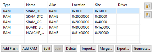
Fig. 59 SRAM_ITC#
Move SRAM_ITC to the first position to make it default.
Build the image. You can find the resulting source image named
Debug\\evkmimxrt10\#\#\_iled\_blinky.axf.
Keil MDK 5
In the toolbar, select iled_blinky debug target.
Open Project > Options > Linker and click Edit to edit the Scatter file.
Close the window and make the following changes in the linker file (changes highlighted):
#define m_interrupts_start 0x00003000
#define m_interrupts_size 0x00000400

#define m_text_start 0x00003400
#define m_text_size 0x0001DC00
Build the image.
You can find the resulting image as
boards\\evkmimxrt10\#\#\\demo\_apps\\led\_blinky\\mdk\\debug\\iled\_blinky.hex.
IAR Embedded Workbench
Select Project < Edit Configurations … > Debug.
Open file MIMXRT10##xxxxx_ram.icf from project root folder and make the following changes:
define symbol m_interrupts_start = 0x00003000;
define symbol m_interrupts_end = 0x000033FF;

define symbol m_text_start = 0x00003400;
define symbol m_text_end = 0x0001FFFF;
On multicore processors set the Processor variant in Project > Options… > General Options > Target, for example Cortex-M7 for iled_blinky_cm7 on RT1176.
Save the changes and build the image.
You can find the resulting image built as boards\evkmimxrt10##\demo_apps\led_blinky\iar\debug\iled_blinky.out.
Image running from external SDRAM#
MCUXpresso IDE
Select Project > Properties - C/C++ Build > Settings > Tool Settings > MCU Linker > Managed Linker Script and check Link application to RAM.
Select Project > Properties - C/C++ Build > Settings > Tool Settings > MCU C Compiler > Preprocessor and add defined symbol SKIP_SYSCLK_INIT=1.
In Project > Properties > C/C++ Build > MCU settings, delete Flash, and modify BOARD_SDRAM to start at 0x80002000 with size 0x1dfe000. Move BOARD_SDRAM to first position to make it default.
Build the image. You can find the resulting source image named Debug\evkmimxrt10##_iled_blinky.axf.
Keil MDK 5
In the toolbar, select iled_blinky sdram_debug target.
Open Project > Options > Linker and click Edit to edit the Scatter file.
Close the window and make the following changes in the linker file (changes highlighted):
#define m_interrupts_start 0x80002000
#define m_interrupts_size 0x00000400

#define m_text_start 0x80002400
#define m_text_size 0x0001DC00

#define m_data_start 0x80020000
#define m_data_size 0x01DE0000
Build the image.
You can find the resulting image as boards\evkmimxrt10##\demo_apps\led_blinky\mdk\sdram_debug\iled_blinky.hex.
IAR Embedded Workbench
Select Project > Edit Configurations … > sdram_debug.
Open file MIMXRT10##xxxxx_sdram.icf from project root folder and make the following changes:
define symbol m_interrupts_start = 0x80002000;
define symbol m_interrupts_end = 0x800023FF;

define symbol m_text_start = 0x80002400;
define symbol m_text_end = 0x8001FFFF;

define symbol m_data_start = 0x80020000;
define symbol m_data_end = 0x8002FFFF;

define symbol m_data2_start = 0x80200000;
define symbol m_data2_end = 0x8023FFFF;

define symbol m_data3_start = 0x80300000;
define symbol m_data3_end = 0x81DFFFFF;

define symbol m_ncache_start = 0x81E00000;
define symbol m_ncache_end = 0x81FFFFFF;
On multicore processors set the Processor variant in Project > Options… > General Options > Target, for example Cortex-M7 for iled_blinky_cm7 on RT1176.
Save the changes and build the image. You can find the resulting image built as
boards\\evkmimxrt10\#\#\\demo\_apps\\led\_blinky\\iar\\sdram\_debug\\iled\_blinky.out.
Connecting the board for RT10xx/RT116x/RT117x devices#
This section contains information about configuring the following evaluation boards and connecting them to SEC:
MIMXRT1010-EVK
MIMXRT1015-EVK
MIMXRT1020-EVK
MIMXRT1024-EVK
MIMXRT1040-EVK
MIMXRT1050-EVKB
MIMXRT1060-EVK
MIMXRT1064-EVK
MIMXRT1160-EVK
MIMXRT1170-EVKB
See Table 22. Boot mode selection for RT1xxx EVK boards for instructions on how to set boot mode using DIP switches.
Make sure that you have J1 (J38 on RT1176, RT1166) set to 3-4 to power the board from USB OTG.
Connect to the J9 (J20 on RT1176, RT1166) port with the USB cable to your PC.
Ensure that SEC is already running with a workspace created for the chosen device. For more information, see Setting up Secure Provisioning Tool.
Make sure that the Boot memory in the toolbar matches the NOR flash used on the EVK board (for exampleflex-spi-nor/ISxxxx).
Set the connection to USB and test the board connection.
Booting from SD card
For booting from an SD card, do the following:
Insert a micro SDHC card into the board.
In the Secure Provisioning Tool, select Boot memory: sdhc_sd_card/SDHC SD card 8 GB in the Toolbar.
Board |
ISP mode |
Flex-SPI NOR (QSPI, HyperFlash) |
Flex-SPI NOR + Encrypted XIP (BEE/OTFAD/IEE) |
SD card |
eMMC |
SEMC NAND |
FlexSPI NAND |
|---|---|---|---|---|---|---|---|
RT1010-EVK |
SW8: 0001 |
SW8: 0010 |
SW8: 0010 |
N/A |
N/A |
N/A |
N/A |
RT1015-EVK |
SW8: 0001 |
SW8: 0010 |
SW8: 1010 |
N/A |
N/A |
N/A |
N/A |
RT1020-EVK |
SW8: 0001 |
SW8: 0010 |
SW8: 1010 |
SW8: 0110 |
N/A |
N/A |
N/A |
RT1024-EVK |
SW8: 0001 |
SW8: 0010 |
SW8: 1010 |
SW8: 0110 |
N/A |
N/A |
N/A |
RT1040-EVK |
SW4: 0001 |
SW4: 0010 |
SW4: 0010 or 0110 |
SW4: 1010 |
N/A |
N/A |
N/A |
RT1050-EVKB |
SW7: 0001 |
SW7: 0110 |
SW7: 0010 or 0110 |
SW7: 1010 |
N/A |
N/A |
N/A |
RT1060-EVK |
SW7: 0001 |
SW7: 0010 |
SW7: 0010 or 0110 |
SW7: 1010 |
N/A |
N/A |
N/A |
RT1064-EVK |
SW7: 0001 |
SW7: 0010 |
SW7: 0010 or 0110 |
SW7: 1010 |
N/A |
N/A |
N/A |
RT1160-EVK |
SW1: 0001 |
SW1: 0010 |
SW1: 0010; SW2: 0100000000 |
SW1: 0010; SW2: 0000001000 |
SW1: 0010 |
SW1: 0010 |
N/A |
RT1170-EVKB |
SW1: 0001 |
SW1: 0010 |
SW1: 0010 |
SW1: 0010 |
SW1: 0010 |
SW1: 0010 |
N/A |
RT1170-EVKB: there is no eMMC on the board, the external eMMC must be connected into the SD card slot.
Booting images for RT10xx/RT116x/RT117x devices#
This section describes the building and writing of bootable images.
You can use several combinations of used memories:
Memory where the image is executed |
Memory where the image is written |
DCD/XMCD needed |
XIP |
|---|---|---|---|
External NOR flash |
External NOR flash |
No |
Yes |
Internal RAM |
External NOR or NAND flash |
No |
No |
Internal RAM |
SD card or eMMC |
No |
No |
SDRAM |
External NOR or NAND flash |
Yes |
No |
SDRAM |
SD card or eMMC |
Yes |
No |
Additional info:
Memory, where the image is executed - Explained in Preparing source image for RT10xx/RT116x/RT117x devices.
Memory, where the image is written - Configured as Boot memory in the SEC Tool.
Note: For RT116x/7x devices, two FlexSPI instances are supported for FlexSPI NOR/NAND boot devices. There is the FLEXSPI_INSTANCE fuse \(BOOT_CFG2\[3\]\) or GPIO boot pin that determines which FlexSPI instance to use. Set a corresponding GPIO boot pin to use Instance 2 without burning the fuse.
See also application note about QSPI flash configuration.
Booting unsigned image#
An unsigned image is typically used for development. It is recommended to start with this boot type before working with secured images to verify that the executable image works properly.
First, build a bootable image:
Make sure that you have selected the Unsigned boot type in the Toolbar.
Switch to the Build image view.
Select the image built in Preparing source image for RT10xx/RT116x/RT117x devices as a Source executable image.
For images executed from SDRAM, configure SDRAM using DCD or XMCD (RT116x/7x). For EVK boards, the following DCD file can be used:
data\targets\MIMXRT1###/evkmimxrt1xxx_SDRAM_dcd.bin. For RT116x/7x, the following XMCD configuration file can be used:data\targets\MIMXRT11##/evkmimxrt11xx_xmcd_semc_sdram_simplified.yaml.Note: For customization of DCD files, refer to Creating/Customizing DCD files.
If needed, open Dual image boot and configure (supported only for RT116x/7x and FlexSPI NOR).
Click the Build image button to build a bootable image.
When the bootable image has been successfully built:
Make sure that the board is in Serial Boot mode.
Switch to the Write image view.
Click the Write image button.
If the write operation was successful, switch boot mode (Table 22. Boot mode selection for RT1xxx EVK boards ) and reset the board.
Booting authenticated (HAB) image#
This section describes the building and writing of an authenticated image. If you want to use an encrypted image, you can skip this step.
In the Toolbar set the Boot type to Authenticated (HAB).
In the Build image view, use the image from Preparing source image for RT10xx/RT116x/RT117x devices as a Source executable image.
For Authentication key select any key, for example, SRK1: IMG1_1+CSF1_1.
If needed, open Dual image boot and configure. (RT116x/7x - FlexSPI NOR)
Select the HAB Closed life cycle.
Click the Build image button.
Check that the bootable image was built successfully.
To write the image, switch to Write image view.
Make sure that the board is set to Serial bootloader ISP mode. See Table 22. Boot mode selection for RT1xxx EVK boards in Connecting the board for RT10xx/RT116x/RT117x devices and reset the board. for more information.
Click the Write image button.
In the following window, confirm to write fuses:
Yes - Continue writing the image and burning fuses.
Note: Burning fuses can only be done once, after that the processor can only execute authenticated images.
No - Do not burn fuses, continue writing the image.
Cancel - Abort writing the image and burning fuses.
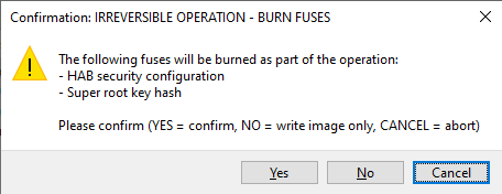
Fig. 60 Burn fuses on i.MX RT1xxx for signed image#
If the write operation was successful, switch boot mode (see Table 22. Boot mode selection for RT1xxx EVK boards ) and reset the board.
Booting encrypted (HAB) authenticated image#
This section describes the building and writing of an encrypted image. This image will be decrypted into RAM during booting operation, so an XIP image cannot be used.
To build the image, do the following:
In the Toolbar set the Boot type to Encrypted (HAB) authenticated.
As a Source executable image, use the image from Preparing source image for RT10xx/RT116x/RT117x devices as a Source executable image.
For Authentication key select any key, for example, SRK1: IMG1_1+CSF1_1.
If needed, open Dual image boot and configure. (RT116x/7x - FlexSPI NOR)
Select the HAB Closed life cycle.
Click the Build image button.
Check that the bootable image was built successfully.
To write the image, do the following:
Switch to Write image view.
Make sure that the board is set to Serial bootloader ISP mode. See Table 22. Boot mode selection for RT1xxx EVK boards for more information.
Click the Write image button.
In the following window, confirm to write fuses:
OK - Continue writing the image and burning fuses.
Note: Burning fuses can only be done once, after that the processor can only execute authenticated images.
Cancel - Abort writing the image and burning fuses.

Fig. 61 Burn fuses on i.MX RT1xxx for HAB encrypted and signed image#
If the write operation was successful, switch boot mode (see Table 22. Boot mode selection for RT1xxx EVK boards ) and reset the board.
Note: Part of the encrypted image is a DEK key blob encrypted using a master key from the processor. This master key is specific for each processor and cannot be used for another processor.
Note: RT101x and RT102x processors do not support running encrypted images in the NOR flash. In case no other booting device is supported for those processors, the Encrypted (HAB) authenticated boot type is not available.
Booting XIP encrypted image (BEE OTPMK) authenticated (RT10xx)#
This section describes the building and writing of an XIP encrypted image using the OTP master key. An authenticated image is built and then encrypted on-the-fly during the write operation. The source image for the encrypted XIP with the BEE feature must be an XIP image.
To build the image, do the following:
In the Toolbar, set the Boot type to XIP encrypted (BEE OTPMK) authenticated.
As a Source executable image, use the image running from external NOR flash from Preparing source image for RT10xx/RT116x/RT117x devices as a Source executable image.
For Authentication key, select any key, for example, SRK1: IMG1_1+CSF1_1.
Click XIP encryption (BEE OTPMK) to open the BEE OTPMK window. In the window, keep the default settings to encrypt the whole image or configure your own FAC Protected Region ranges within the first BEE encrypted region.
Select the HAB Closed life cycle.
Click the Build image button.
Check that the bootable image was built successfully.
To write the image, do the following:
Switch to Write image view.
Make sure that the board is set to Serial bootloader ISP mode. See Table 22. Boot mode selection for RT1xxx EVK boards for more information.
Enable XIP encryption by setting a corresponding GPIO pin (see Table 22. Boot mode selection for RT1xxx EVK boards for more information).
Click the Write image button.
In the following window, confirm to write fuses:
OK - Continue writing the image and burning fuses.
Note: Burning fuses can only be done once, after that the processor can only execute authenticated images.
Cancel - Abort writing the image and burning fuses.
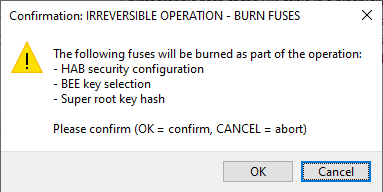
Fig. 62 Burn fuses on i.MX RT10xx for BEE OTPMK encrypted image#
If the write operation was successful, switch boot mode (see Table 22. Boot mode selection for RT1xxx EVK boards ) and reset the board.
Note: Step 5 can be replaced by setting the EncryptedXIP fuse in the OTP configuration.
Booting XIP encrypted image (BEE user keys) unsigned (RT10xx)#
This section describes the building and writing of an XIP encrypted image using user keys. The image itself is built in two steps. First, the unsigned bootable image is built and then this unsigned image is encrypted for use with enabled encrypted XIP. The source image for the encrypted XIP with the BEE feature must be an XIP image.
To build the image, do the following:
In the Toolbar, set the Boot type to XIP encrypted (BEE user keys) unsigned.
As a Source executable image, use the image external NOR flash from Preparing source image for RT10xx/RT116x/RT117x devices as a Source executable image.
Click XIP encryption (BEE user keys) to open the BEE user keys window. In the window, keep the default settings to encrypt the whole image, or edit User keys data to provide your specific key. Furthermore, the window allows you to configure additional BEE parameters (Both regions (engines), user key(s) for regions, FAC Protected Region ranges, random key generation).
Click the Build image button.
Check that the bootable image was built successfully.
To write the image, do the following:
Switch to Write image view.
Make sure that the board is set to Serial bootloader ISP mode. See Table 22. Boot mode selection for RT1xxx EVK boards for more information.
Enable XIP encryption by setting a corresponding GPIO pin (see Table 22. Boot mode selection for RT1xxx EVK boards for more information).
Click the Write image button.
In the following window, confirm to write fuses:
OK - Continue writing the image and burning fuses.
Note: Burning fuses can only be done once, after that it is not possible to modify them.
Cancel - Abort writing the image and burning fuses.

Fig. 63 Burn fuses on i.MX RT10xx for BEE encrypted with user keys#
If the write operation was successful, switch boot mode (see Table 22. Boot mode selection for RT1xxx EVK boards ) and reset the board.
Note: Step 5 can be replaced by setting the EncryptedXIP fuse in the OTP configuration.
Booting XIP encrypted image (BEE user keys) authenticated (RT10xx)#
This section describes the building and writing of an XIP encrypted image using user keys. The image itself is built in two steps. First, the authenticated bootable image is built and then this authenticated image is encrypted for use with enabled encrypted XIP. The source image for the encrypted XIP with the BEE feature must be an XIP image.
To build the image, do the following:
In the Toolbar set the Boot type to XIP encrypted (BEE user keys) authenticated.
As a Source executable image, use the image external NOR flash from Preparing source image for RT10xx/RT116x/RT117x devices as a Source executable image.
For Authentication key, select any key, for example, SRK1: IMG1_1+CSF1_1.
Click XIP encryption (BEE user keys) to open the BEE user keys window. In the window, keep the default settings to encrypt the whole image, or edit user keys data to provide your specific key. Additionally, the window allows you to configure additional BEE parameters (Both regions (engines), user key(s) for regions, FAC Protected Region ranges, random key generation).
Select the HAB Closed life cycle.
Click the Build image button.
Check that the bootable image was built successfully.
To write the image, do the following:
Switch to Write image view.
Make sure that the board is set to Serial bootloader ISP mode. See Table 22. Boot mode selection for RT1xxx EVK boards in Connecting the board for RT10xx/RT116x/RT117x devices for more information.
Enable XIP encryption by setting a corresponding GPIO pin. See Table 22. Boot mode selection for RT1xxx EVK boards in Connecting the board for RT10xx/RT116x/RT117x devices for more information).
Click the Write image button.
In the following window, confirm to write fuses:
OK - Continue writing the image and burning fuses.
Note: Burning fuses can only be done once, after that the processor can only execute authenticated images.
Cancel - Abort writing the image and burning fuses.
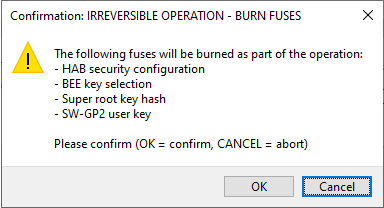
Fig. 64 Burn fuses on i.MX RT10xx for BEE encrypted and signed image#
If the write operation was successful, switch boot mode (see Preparing source image for RT10xx/RT116x/RT117x devices and reset the board.
Note: Step 5 can be replaced by setting the EncryptedXIP fuse in the OTP configuration.
Booting XIP encrypted image (OTFAD OTPMK) authenticated (RT10xx)#
This section describes building and writing of an XIP encrypted image using the OTP master key. The authenticated image is built and then encrypted on-the-fly during the write operation. The source image for the encrypted XIP with the OTFAD feature must be an XIP image.
To build the image, do the following:
In the Toolbar, set the Boot type to XIP encrypted (OTFAD OTPMK) authenticated.
As a Source executable image, use the image running from external NOR flash from Preparing source image for RT10xx/RT116x/RT117x devices as a Source executable image.
For Authentication key, select any key, for example, SRK1: IMG1_1+CSF1_1.
Click XIP encryption (OTFAD OTPMK) to open the OTFAD OTPMK window. In the window, keep the default settings to encrypt the whole image or configure your own Protected Region ranges.
Select the HAB Closed life cycle.
Click the Build image button.
Check that the bootable image was built successfully.
To write the image, do the following:
Switch to Write image view.
Make sure that the board is set to Serial bootloader ISP mode. See Table 22. Boot mode selection for RT1xxx EVK boards in Connecting the board for RT10xx/RT116x/RT117x devices for more information.
Click the Write image button.
In the following window, confirm to write fuses:
OK - Continue writing the image and burning fuses.
Note: Burning fuses can only be done once, after that the processor can only execute authenticated images.
Cancel - Abort writing the image and burning fuses.
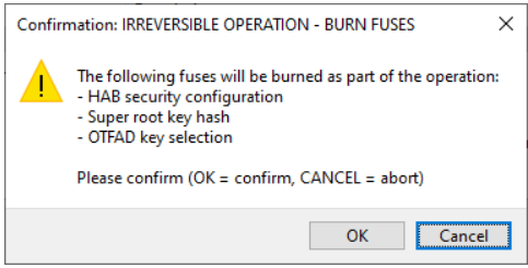
Fig. 65 Burn fuses on i.MX RT10xx for OTFAD encrypted and signed image#
If the write operation was successful, switch boot mode. See Table 22. Boot mode selection for RT1xxx EVK boards in Connecting the board for RT10xx/RT116x/RT117x devices and reset the board.
Booting OTFAD encrypted image unsigned with user keys.#
This section describes the building and writing of an OTFAD encrypted image. The image itself is built in two steps.
To build the image, do the following:
In the Toolbar set Boot Type to Encrypted, (OTFAD) unsigned for RT116x/7x or XIP encrypted (OTFAD user keys) unsigned for RT10xx.
As a Source executable image, use the image external NOR flash from Preparing source image for RT10xx/RT116x/RT117x devices as a Source executable image.
Click OTFAD encryption/XIP encryption (OTFAD user keys) to open the OTFAD Configuration window. In the window set random keys. The window allows you to configure the number of OTFAD regions (contexts), KEK source (OTP or PUF KeyStore), KEK, Key scramble, user keys for regions, regions ranges, random key generation.
Open OTP configuration and review the settings and fix any reported problems.
Click the Build image button.
Check that the bootable image was built successfully.
To write the image, do the following:
Switch to Write image view.
Make sure that the board is set to Serial bootloader ISP mode. See Table 22. Boot mode selection for RT1xxx EVK boards in Connecting the board for RT10xx/RT116x/RT117x devices for more information.
Reset the board if the OTFAD KEK source is set to PUF KeyStore. It is necessary so that the key store is enrolled successfully.
Enable XIP encryption (RT116x/7x) by setting a corresponding GPIO pin (see Table 22. Boot mode selection for RT1xxx EVK boards in Connecting the board for RT10xx/RT116x/RT117x devices for more information).
Click the Write image button.
In the following window, confirm to write fuses:
OK - Continue writing the image and burning fuses.
Note: Burning fuses can only be done once, after that it is not possible to modify them.
Cancel - Abort writing the image and burning fuses.
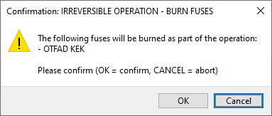
Fig. 66 Burn fuses on i.MX RT10xx/RT116x/RT117x for OTFAD encrypted image#
If the write operation was successful, switch boot mode (see Table 22. Boot mode selection for RT1xxx EVK boards in Connecting the board for RT10xx/RT116x/RT117x devices ) and reset the board.
Note: Step 6 (RT116x/7x) can be replaced by setting the ENCRYPT_XIP_EN fuse in the OTP configuration.
Booting OTFAD encrypted image authenticated with user keys#
This section describes the building and writing of an OTFAD encrypted image. The image itself is built in two steps. First, the authenticated bootable image is built and then this authenticated image is encrypted for use with OTFAD. The source image for the OTFAD feature must be an XIP image.
To build the image, do the following:
In the Toolbar set Boot type to Encrypted (OTFAD) authenticated for RT116x/7x or XIP encrypted (OTFAD user keys) authenticated for RT10xx.
As a Source executable image, use the image external NOR flash from Preparing source image for RT10xx/RT116x/RT117x devices as a Source executable image.
Ensure that you have keys generated in the PKI management view. For more information, see PKI management.
For Authentication key select any key, for example, SRK1: IMG1_1+CSF1_1.
Click OTFAD encryption / XIP encryption (OTFAD user keys) to open the OTFAD configuration window. In the window set random keys. The window allows you to configure the number of OTFAD regions (contexts), KEK source (OTP or KeyStore), KEK, Key scramble, user keys for regions, regions ranges, random key generation.
Select the HAB Closed life cycle.
Open OTP configuration and review the settings and fix any reported problems.
Click the Build image button.
Check that the bootable image was built successfully.
To write the image, do the following:
Switch to Write image view.
Make sure that the board is set to Serial bootloader ISP mode. See Table 22. Boot mode selection for RT1xxx EVK boards in Connecting the board for RT10xx/RT116x/RT117x devices for more information.
Reset the board if the OTFAD KEK source is set to KeyStore. It is necessary so that the KeyStore is enrolled successfully
Enable XIP encryption (RT116x/7x) by setting a corresponding GPIO pin (see Table 22. Boot mode selection for RT1xxx EVK boards in Connecting the board for RT10xx/RT116x/RT117x devices for more information).
Click the Write image button.
In the following window, confirm to write fuses:
OK - Continue writing the image and burning fuses.
Note: Burning fuses can only be done once, after that the processor can only execute authenticated images.
Cancel - Abort writing the image and burning fuses.

Fig. 67 Burn fuses on i.MX RT10xx/RT116x/RT117x for OTFAD encrypted and sized image#
If the write operation was successful, switch boot mode (see Table 22. Boot mode selection for RT1xxx EVK boards in Connecting the board for RT10xx/RT116x/RT117x devices ) and reset the board.
Note: Step 6 (RT116x/7x) can be replaced by setting the ENCRYPT_XIP_EN fuse in OTP configuration.
Booting IEE encrypted image unsigned (RT116x/7x)#
This section describes how to build and write an IEE encrypted image. The image itself is built in two steps. First, the unsigned bootable image is built, and then this unsigned image is encrypted for use with the IEE. The source image for the IEE feature must be an XIP image.
To build the image, do the following:
In the Toolbar set the Boot type to Encrypted (IEE) unsigned.
As a Source executable image, use the image external NOR flash from Preparing source image for RT10xx/RT116x/RT117x devices as a Source executable image.
Click IEE encryption to open the IEE Configuration window. In the window set random keys. The window allows you to configure the number of IEE regions (contexts), KEK, AES encryption mode, and user keys for regions, regions ranges, random key generation.
Open the OTP configuration, review the settings, and fix any reported problems.
Click the Build image button.
Check that the bootable image was built successfully.
To write the image, do the following:
Switch to the Write image view.
Make sure that the board is set to Serial bootloader ISP mode. See Table 22. Boot mode selection for RT1xxx EVK boards in Connecting the board for RT10xx/RT116x/RT117x devices for more information.
Reset the board. It is required for successful key store enrollment.
Enable XIP encryption by setting a corresponding GPIO pin (see Table 22. Boot mode selection for RT1xxx EVK boards in Connecting the board for RT10xx/RT116x/RT117x devices for more information).
Click the Write image button.
In the following window, confirm to write fuses:
OK - Continue writing the image and burning fuses.
Note: Burning fuses can only be done once, after that it is not possible to modify them.
Cancel - Abort writing the image and burning fuses.
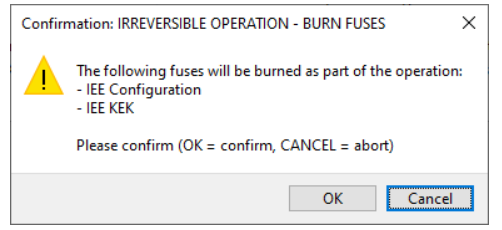
Fig. 68 Burn fuses on RT116x/7x for IEE encrypted image#
If the write operation was successful, switch boot mode (see Table 22. Boot mode selection for RT1xxx EVK boards in Connecting the board for RT10xx/RT116x/RT117x devices) and reset the board.
Note: Step 5 can be replaced by setting the ENCRYPT_XIP_EN fuse in the OTP configuration.
Booting IEE encrypted image authenticated (RT116x/7x)#
This section describes how to build and write an IEE encrypted image. The image itself is built in two steps. First, the unsigned bootable image is built, and then this unsigned image is encrypted for use with the IEE. The source image for the IEE feature must be an XIP image.
To build the image, do the following:
In the Toolbar set the Boot type to Encrypted (IEE) authenticated.
As a Source executable image, use the image external NOR flash from Preparing source image for RT10xx/RT116x/RT117x devices as a Source executable image.
Ensure that you have keys generated in the PKI management view. For more information, see section PKI management.
For Authentication key select any key, for example, SRK1: IMG1_1+CSF1_1.
Click IEE encryption to open the IEE Configuration window. In the window set random keys. The window allows you to configure the number of IEE regions (contexts), KEK, AES encryption mode, and user keys for regions, regions ranges, random key generation.
Select the HAB Closed life cycle.
Open the OTP configuration, review the settings, and fix any reported problems.
Click the Build image button.
Check that the bootable image was built successfully.
To write the image, do the following:
Switch to Write image view.
Make sure that the board is set to Serial bootloader ISP mode. See Table 22. Boot mode selection for RT1xxx EVK boards in Connecting the board for RT10xx/RT116x/RT117x devices for more information.
Reset the board. It is required for successful key store enrollment.
Enable XIP encryption by setting a corresponding GPIO pin (see Table 22. Boot mode selection for RT1xxx EVK boards in Connecting the board for RT10xx/RT116x/RT117x devices for more information).
Click the Write image button.
In the following window, confirm to write fuses:
OK - Continue writing the image and burning fuses.
Note: Burning fuses can only be done once, after that it is not possible to modify them.
Cancel - Abort writing the image and burning fuses.
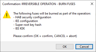
Fig. 69 Burn fuses on RT116x/7x for IEE encrypted and signed image#
If the write operation was successful, switch boot mode (see Table 22. Boot mode selection for RT1xxx EVK boards in Connecting the board for RT10xx/RT116x/RT117x devices) and reset the board.
Note: Step 6 can be replaced by setting the ENCRYPT_XIP_EN fuse in the OTP configuration.
Creating/Customizing DCD files#
It is recommended to use MCUXpresso Config Tools or MCUXpresso IDE to prepare a DCD binary file.
In any of the tools open any project/configuration for the selected processor.
Import existing DCD configuration from an SDK source code by selecting main menu > File > Import > MCUXpresso Config Tools > Import Source.
Select the file from SDK package in boards\evkmimxrt10##\xip\evkmimxrt10##_sdram_ini_dcd.c.
Switch to the Device Configuration tool by selecting main menu > Config Tools > Device Configuration.
In the toolbar of the DCD view, select Output Format to binary.
Navigate to Code Preview and in the toolbar click the Export button and select the location where to generate a binary file.
Note: Refer to the documentation of the Device Configuration Tool for more information.
RT118x device workflow#
This section describes the RT118x device workflow in detail.
Preparing source image for RT118x devices#
In this step, select the target memory where the image will be executed. The following options are available for RT118x devices:
Image running from an external NOR flash
It is the so-called XIP(eXecution In Place) image. It means that the image is executed directly from the memory where it is.
Image running in RAM
This image can be on an SD card/eMMC, in external flash (FlexSPI NOR, FlexSPI NAND). During boot, it will be copied into RAM and executed from there, or alternatively, it can be loaded into RAM using the serial downloader. The following RAM types are supported:
internal RAM
SDRAM
HyperRAM
The source image preparation is similar to RT116x/7x, see Preparing source image for RT10xx/RT116x/RT117x devices. Some RT118x specifics:
Select an example for core cm33 and then set the target to Cortex-M33.
ELE firmware is distributed in MCUXpresso SDK in the ‘ELE crypto’ component, typically the
firmware\edgelock\mxrt1180-ahab-container.imgfile.For MCUXpresso IDE and CM33 image in internal RAM, the following project modifications are needed. These changes were verified in MCUXpresso IDE version 25.06 in conjunction with MCUXpresso SDK version 25.09:
ensure that the ITC is the first RAM listed in the available memory areas (see project Properties > C/C++ Build > MCU settings)
change global data placement and “CodeQuickAccess” to DTC_cm33 and ensure the “Link application to RAM” checkbox is selected (see project Properties > C/C++ Build > Settings > Managed Linker Script)
change
data_init()andbss_init()functions instartup_mimxrt1189_cm33.ccode:
__attribute__ ((section(".after_vectors.init_data")))
void data_init(unsigned int romstart, unsigned int start, unsigned int len) {
    if (start == romstart)
        return;
    unsigned int *pulDest = (unsigned int*) start;
    unsigned int *pulSrc = (unsigned int*) romstart;
    unsigned int loop;
    for (loop = 0; loop < len; loop = loop + 4)
        *pulDest++ = *pulSrc++;
}

__attribute__ ((section(".after_vectors.init_bss")))
void bss_init(unsigned int start, unsigned int len) {
    unsigned int *pulDest = (unsigned int*) start;
    unsigned int loop;
    for (loop = 0; loop < len; loop += 4, ++pulDest)
        if (*pulDest != 0)
	        *pulDest = 0;
}
Connecting the board for RT118x devices#
This section contains information about configuring the RT118x boards and connecting them to the SEC Tool.
EVK/FRDM boards |
Power selection jumper |
USB |
UART |
FlexSPI instance 1 |
FlexSPI instance 2 |
|---|---|---|---|---|---|
MIMXRT1180-EVK |
J1 (3-4 over USB; 7-8 over UART) |
J33 |
J53 |
FlexSPI NOR |
HyperRAM |
FRDM-IMXRT1186 |
J4 (3-4 over USB; 5-6 over UART) |
J63 |
J23 |
HyperRAM |
FlexSPI NOR |
Note:
For FRDM-IMXRT1186 the SEC Tool automatically configures booting from FlexSPI instance 2 (FlexSPI NOR), which results in the BOOT_CFG2 fuse being burnt
See Table 25. Boot mode selection for RT118x EVK boards in Connecting the board for RT118x devices for instructions on how to set boot mode using DIP switches.
Make sure that you have the power selection jumper set to 3-4 to power the board from USB.
Connect the board over the USB cable to your PC over UART or USB.
Ensure that SEC is already running with a workspace created for the chosen device. For more information, see Setting up Secure Provisioning Tool.
Make sure that the Boot device in the Boot Memory Configuration matches the FlexSPI NOR flash used on the EVK/FRDM board.
Set the connection to your selected connection (USB or UART) and test the board connection.
Booting from SD card#
For booting from an SD card, do the following:
Insert a micro SDHC card into the board.
Select SD card, SDHC SD-card 8GB USDHC1 in the Boot Memory Configuration.
Booting from eMMC#
For booting from an eMMC, do the following:
eMMC can be installed on board, or it is possible to connect eMMC through SD slot by SD/eMMC adapter.
Select eMMC, SDHC eMMC 8 GB USDHC1 in the Boot Memory Configuration.
Booting from serial downloader#
For booting from a serial downloader, do the following:
Set ISP boot mode on the board boot mode switch
Select RAM via serial downloader in the Boot Memory Configuration
Boot mode selection for RT118x EVK boards#
Board |
ISP mode |
Flex-SPI NOR |
SD card/ eMMC |
FlexSPI NAND |
|---|---|---|---|---|
RT1180-EVK |
SW5: x001 |
SW5: x100 |
SW5: x011 |
SW5: x101 (N/A) |
FRDM-IMXRT1186 |
J60: 100 |
J60: 001 |
J60: 110 |
J60: 101 (N/A) |
Booting images for RT118x devices#
This section describes the combinations of used memories for the boot.
Memory where the image is executed |
Boot memory: Memory where the image is written |
XMCD needed |
XIP |
|---|---|---|---|
External NOR flash |
External NOR flash |
No |
Yes |
Internal RAM |
External NOR or NAND flash |
No |
No |
Internal RAM |
SD card or eMMC |
No |
No |
Internal RAM |
Serial downloader |
No |
No |
SDRAM/HyperRAM |
Serial downloader |
Yes |
No |
SDRAM/HyperRAM |
External NOR or NAND flash |
Yes |
No |
SDRAM/HyperRAM |
SD card or eMMC |
Yes |
No |
Note:
Memory, where the image is executed is explained in Preparing source image for LPC55(S)0x/1x/2x/6x devices.
Memory where the image is written is configured as Boot Memory in the SEC Tool.
For all boot devices other than the Serial downloader, the bootable image is in sparse (.simg) format. In case of Serial downloader the image is built as a binary (.bin) image.
Booting unsigned image#
An unsigned image is typically used for development. Start with this boot type before working with secured images to verify that the executable image works properly.
First, build a bootable image:
Make sure that you have selected the Unsigned boot type in the Toolbar.
Switch to the Build image view.
Select the image built in Preparing source image for RT118x devices as a Source executable image.
For images executed from SDRAM/HyperRAM, configure SEMC SDRAM / FlexSPI HyperRAM using XMCD. For EVK boards, the following XMCD configuration files can be used: <SEC>/sample_data/targets/MIMXRT118#/evkmimxrt118#_xmcd_*_simplified.yaml.
If needed, open Dual image boot and configure.
Click the Build image button to build a bootable image.
When the bootable image has been successfully built:
Make sure that the board is in Serial bootloader ISP mode.
Switch to the Write image view.
Click the Write image button.
If the write operation was successful, switch boot mode (see Boot mode selection for RT118x EVK boards) and reset the board.
Booting signed image#
This section describes the building and writing of a signed image. Keys generated in the PKI management view are needed in this step. For more information about generating keys, see Generate keys. If you want to use an encrypted image, you can skip this step.
First, build a bootable image:
In the Toolbar set Boot type to Signed.
In the Build image view, use the image from Preparing source image for RT118x devices as a Source executable image.
For Authentication key select any key, for example, SRK1.
Select the OEM Closed life cycle.
Click the Build image button.
Check that the bootable image was built successfully.
To write the image, switch to Write image view.
Make sure that the board is set to Serial bootloader ISP mode. See Boot mode selection for RT118x EVK boards for more information.
Click the Write image button.
In the following window, confirm to write fuses:
OK - Continue writing the image and burning fuses.
Cancel - Abort writing the image and burning fuses.
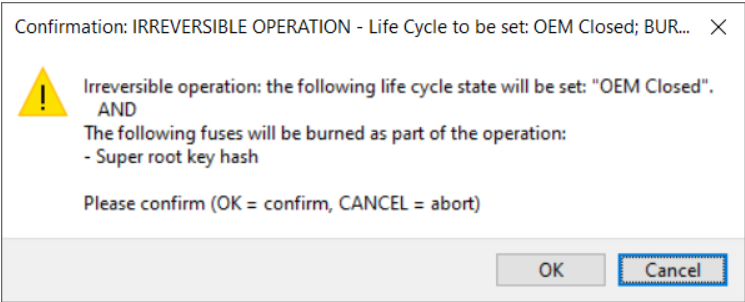
Fig. 70 Burn fuses on i.MX RT118x for signed image#
If the write operation was successful, switch boot mode (see Boot mode selection for RT118x EVK boards) and reset the board.
Booting encrypted (AHAB) image#
This section describes the building and writing of an encrypted image. This image is decrypted into RAM during booting operation, so an XIP image cannot be used. The keys generated in the PKI management view are needed in this step. For more information about generating keys, see Generate keys.
To build the image, do the following:
In the Toolbar set the Boot type to Encrypted (AHAB).
As a Source executable image, use the image from Preparing source image for RT118x devices as a Source executable image.
For Authentication key select any key, for example, SRK1.
Select the OEM Closed life cycle.
Click the Build image button.
Check that the bootable image was built successfully.
To write the image, do the following:
Switch to the Write image view.
Make sure that the board is set to Serial bootloader ISP mode. See Boot mode selection for RT118x EVK boards for more information.
Click the Write image. button.
In the following window, confirm to write fuses:
OK - Continue writing the image and burning fuses.
Cancel - Abort writing the image and burning fuses.
If the write operation was successful, switch boot mode (see Boot mode selection for RT118x EVK boards) and reset the board.
Note: Part of the encrypted image is a DEK key blob encrypted using a master key from the processor. This master key is specific for each processor and cannot be used for another processor. DEK key blob is generated during write and the AHAB image is then updated with this processor-specific key blob.
Booting OTFAD encrypted image#
This section describes the building and writing of an OTFAD encrypted image. The image itself is built in two steps. First, the unsigned/signed AHAB image is built and then this AHAB image is encrypted for use with OTFAD. The source image for the OTFAD feature must be an XIP image. The Keys generated in the PKI management view are needed in this step. For more information about generating keys, see Generate keys.
To build the image, do the following:
In the Toolbar set the Boot type to Encrypted (OTFAD) signed or Encrypted (OTFAD) unsigned.
As a Source executable image, use the image external NOR flash from Preparing source image for RT118x devices as a Source executable image.
For Authentication key select any key, for example, SRK1.
Click OTFAD encryption to open the OTFAD configuration window. In the window set random keys. The window allows you to configure the number of OTFAD regions (contexts), KEK source (OTP or DUK), KEK, Key scramble, user keys for regions, regions ranges, random key generation.
Select the OEM Closed life cycle.
Open the OTP configuration and review the settings and fix any reported problems.
Click the Build image button.
Check that the bootable image was built successfully.
To write the image, do the following:
Switch to Write image view.
Make sure that the board is set to Serial bootloader ISP mode. See Boot mode selection for RT118x EVK boards for more information.
Click the Write image button.
In the following window, confirm to write fuses:
OK - Continue writing the image and burning fuses.
Cancel - Abort writing the image and burning fuses.
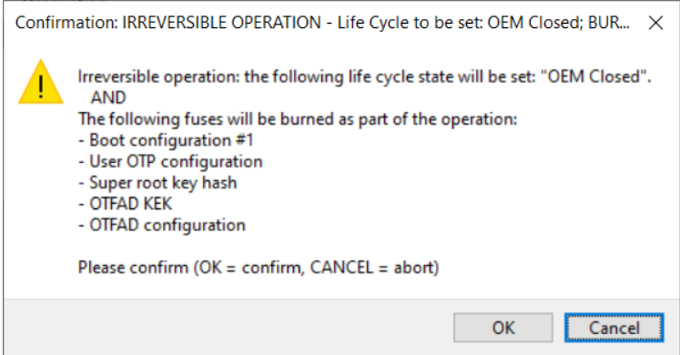
Fig. 71 Burn fuses on i.MX RT118x for OTFAD encrypted image#
If the write operation was successful, switch boot mode (see Boot mode selection for RT118x EVK boards) and reset the board.
Booting IEE encrypted#
This section describes the building and writing of an IEE encrypted image. The image itself is built in two steps. First, the unsigned/signed AHAB image is built and then this AHAB image is encrypted for use with IEE. The source image for the IEE feature must be an XIP image. The Keys generated in the PKI management view are needed in this step. For more information about generating keys, see Generate keys.
To build the image, do the following:
In the Toolbar set the Boot type to Encrypted (IEE) signed or Encrypted (IEE) unsigned.
As a Source executable image, use the image external NOR flash from Preparing source image for RT118x devices as a Source executable image.
For Authentication key select any key, for example, SRK1.
Click IEE encryption to open the IEE configuration window. In the window set random keys. The window allows you to configure the number of IEE regions (contexts), AES encryption mode, and user keys for regions, regions ranges, random key generation.
Select the OEM Closed life cycle.
Open the OTP configuration and review the settings and fix any reported problems.
Click the Build image button.
Check that the bootable image was built successfully.
To write the image, do the following:
Switch to the Write image view.
Make sure that the board is set to Serial bootloader ISP mode. See Boot mode selection for RT118x EVK boards for more information.
Click the Write image button.
In the following window, confirm to write fuses:
OK - Continue writing the image and burning fuses.
Cancel - Abort writing the image and burning fuses.
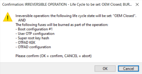
Fig. 72 Burn fuses on i.MX RT118x for IEE encrypted image#
If the write operation was successful, switch boot mode (see Boot mode selection for RT118x EVK boards) and reset the board.
Booting multicore images#
This section describes how to build and write an image for multiple cores (Cortex M33 and Cortex M7). Only Cortex M33 is a bootable core. The source image used for Cortex M33 must trigger the second core in the code (Cortex M7). See demo_apps\multicore_trigger example in the SDK package for RT118x.
To build multicore images, do the following:
In this example, the Cortex M7 XIP image runs from external Flash (start address 0x2800B000) and the Cortex M33 image runs from internal RAM (start address 0xFFE0000):
Set the Source executable image (image for Cortex M33) in the Build tab.
Open the Additional User/OEM Image dialog via the Additional images button (the application binary image is automatically filled up).
Specify a standalone Cortex M7 executable binary image running from the flash memory and set the following values:
Image offset - 0xA000. It is calculated as: Load address (0x2800B000) - FlexSPI NOR base address (0x28000000) - AHAB image offset in FlexSPI NOR (0x1000)
Load address - 0x2800B000
Entry point - 0x2800B000
Core Id - cortex-m7
Image type - executable
Close the dialog by clicking the OK button.
Click the Build image button.
In this example, the Cortex M7 image runs from internal ITCM RAM (start address 0x0) and the Cortex M33 XIP image runs from external flash (start address 0x2810B000). This use case requires additional fuses, so the internal RAM is properly accessible.
Set the Source executable image (image for Cortex M33) in the Build tab.
Open the Additional User/OEM Image dialog via the Additional images button (the application binary image is automatically filled up).
Specify a standalone Cortex M7 executable binary image running from ITCM RAM and set the following values:
Image offset - 0x10F400 - this can be any value, which does not overlap with other image (in this example the image was placed directly after the Cortex M33 image)
Load address - 0x303C0000 (secured alias of CM7 ITCM in the CM33 core address space)
Entry point - 0x0 (the start addresses of the image in the CM7 address space)
Core Id - cortex-m7
Image type - executable
Close the dialog by clicking the OK button.
Open the OTP Configuration dialog by clicking the OTP configuration button in the left-bottom corner.
Set POR_PRELOAD_MC7_TCM_ECC and RELEASE_M7_RST_STAT fuses (BOOT_CFG7) to 1 and fix any reported problems.
Close the dialog via the OK button.
Click the Build image button.
Note: The write process of the multicore images is the same as for Booting IEE encrypted.
Life cycle for RT118x device workflow#
The default life cycle, which should be used for development, is OEM Open. Before you deploy the application, set the OEM Closed or OEM Locked life cycle (see documentation for the target processor for detailed description).
Note: Change of the life cycle is irreversible.
Once the processor is in “OEM Closed” or “OEM Locked” mode:
The tool processor does not allow burn fuses via blhost. The application can still be updated.
The processor can only execute signed images
Firmware version#
The firmware version value is included in the AHAB container header, field Fuse version. This version value is fused indirectly through the ELE commit API when the AHAB container is authenticated. This commit API must be called from the application itself.
The AHAB image with a lower fuse version than the version fused cannot be loaded during booting.
The firmware version is supported for signed images only.
RT5xx/6xx device workflow#
This section describes the RT5xx/6xx device workflow in detail.
Preparing source image RT5xx/6xx devices#
In this step, you must select the target memory where the image will be executed.
Supported boot memories are NOR flash, SD card, and eMMC.
The following boot types are available for RT5xx/6xx processors:
Image running in external flash: The XIP image (eXecuted In Place)
Image running in internal RAM: The image is copied from FLASH, SD card, or eMMC to RAM before the execution
It is recommended to use the gpio_led_output example for the verification that the image is started properly. By default, this example triggers LED blinking only if the user button is clicked, but it is possible to modify it to blink continuously.
Image running in external flash#
The gpio_led_output example is linked into external flash by default. Disable the XIP Boot header, as it will be created by SEC.
MCUXpresso IDE
Optional step: go to Project > Properties > C/C++ Build > Settings > MCU C Compiler > Preprocessor > Defined symbols and set
BOOT_HEADER_ENABLEto0.Build the image. You will find the resulting source image named as
Debug\\evkmimxrt685_gpio_led_output.axf. It can be used as an input for the bootable image in the SEC Tool.
Keil MDK
In the Toolbar, select gpio_output_flash_debug target.
Optional step: in Project > Options > “*C/C++*” disable define symbol
BOOT_HEADER_ENABLE=0(set to 0).In Project > Options > Output select the Create HEX file checkbox.
Double-check that the application is linked to 0x8001000. If not, the following fix must be applied to the linker as a workaround for the problem:
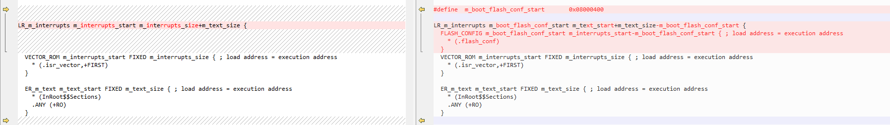
Fig. 73 Keil MDK workaround#
Build the image. You will find the output image as
boards\evkmimxrt685\driver_examples\gpio\led_output\mdk\flash_debug\gpio_led_output.out.
IAR Embedded Workbench
In Project > Edit Configurations …, select
flash_debug.Optional step: in Project Options > C/C++ Compiler > Preprocessor > Defined Symbols, add or change the existing
BOOT_HEADER_ENABLEdefine to0.Build the image. You will find the output image as
boards\evkmimxrt###\driver_examples\gpio\led_output\iar\flash_debug\gpio_led_output.out.
Image running in internal RAM#
MCUXpresso IDE
Optional step: Go to Project > Properties > C/C++ Build > Settings > MCU C Compiler > Preprocessor > Defined symbols and set
BOOT_HEADER_ENABLEto0.Select Project > Properties - C/C++ Build > Settings > Tool Settings > MCU Linker > Managed Linker Script and check
Link application to RAM.Build the image. You will find the built image as
Debug\evkmimxrt685_gpio_led_output.axf. You can later use it as a Source executable image by SEC.
Keil MDK
Because example projects for MDK are not built into RAM, you must manually modify the linker file. Generic description of such changes is not documented yet.
IAR Embedded Workbench
In Project > Edit Configurations …, select
debug.Optional step: In Project Options > C/C++ Compiler > Preprocessor > Defined Symbols, add or change the existing
BOOT_HEADER_ENABLEdefine to0.Build the image. You will find the output image built as
boards\evkmimxrt###\driver_examples\gpio\led_output\iar\debug\gpio_led_output.out.
Connecting the board for RT5xx/6xx devices#
This section contains information about configuring the following evaluation boards and connecting them to SEC:
MIMXRT595-EVK
MIMXRT685-AUD-EVK
Board |
ISP mode |
FlexSPI Boot |
SD card |
eMMC |
|---|---|---|---|---|
MIMXRT595-EVK |
SW7[1:3]: 100 (UART, SPI, I2C) |
SW7[1:3]: 001 |
SW7[1:3] 011 |
SW7[1:3] 110 |
MIMXRT685-AUD-EVK |
SW5[1:3]: 100 |
SW5[1:3]: 101 |
SW5[1:3] 011 |
SW5[1:3] 110 |
Note: 1 means that the switch is ON, 0 means that the switch is OFF.
Switch the board to ISP Mode and reset. For more information, see the above table.
Connect to the J7 port with the USB cable to your PC.
Ensure that you have started SEC with a new workspace. For more information, see Setting up Secure Provisioning Tool.
Set the connection to USB and test the board connection.
Booting from SD card:
For booting from an SD card, do the following:
Insert the SDHC card into the board in the Secure Provisioning Tool
Select the Boot memory: sd_card/SDHC SD card 8 GB in the Toolbar.
SDHC power cycle must be set to ENABLED for evk boards
Booting from eMMC:
For booting from an eMMC, do the following:
eMMC can be installed on board, or it is possible to connect eMMC through SD slot by SD/eMMC adapter.
Select Boot memory: eMMC/SDHC eMMC 8 GB in the Toolbar.
Booting images for RT5xx/6xx devices#
This chapter describes the building and writing of plain and signed bootable images.
Booting a plain/plain with CRC image#
A plain image is typically used for development. It is recommended to start with this boot type before working with secured images to verify that the executable image works properly.
To build a bootable image, follow these steps:
In the Toolbar, select Plain unsigned or Plain with CRC in Boot type.
Switch to the Build image view.
Select image build in Preparing source image RT5xx/6xx devices as a Source executable image. If needed, open the Dual image boot and configure. If configured, open the OTP configuration and review all reported problems. For fuse BOOT_CFG[3] being locked after write, it is necessary to specify the whole value as it is programmed only once.
Click the Build image button to build a bootable image.
When the bootable image has been successfully built:
Connect the board, see Connecting the board RT5xx/6xx devices.
Switch to the Write image view.
Reset the board. If the write script is executed twice without resetting the board, the configuration of external memory may fail unless the fuse with the QSPI reset pin is not burnt.
Click the Write image button.
If the write operation was successful, switch boot mode to FlexSPI boot (Table: Boot configurations of the RT5xx/6xx EVK boards in Connecting the board RT5xx/6xx devices) and reset the board.
Booting plain signed image using shadow registers#
This section describes the building and writing of an authenticated image.
In the Toolbar set Boot type to Plain signed.
In the Build image view, use the image from Preparing source image RT5xx/6xx devices as a Source executable image.
Ensure that you have keys generated in the PKI management view. For more information, see PKI management.
For Authentication key, select any key, for example, ROT1: IMG1_1.
As a Key source, select OTP or KeyStore. KeyStore represents a higher security level, as PUF is used. See Securing the processor for the limitations.
Generate a random User key and SBKEK.
If needed, open Dual image boot and configure.
Select the Development life cycle.
Open OTP configuration and review all reported problems. For fuses BOOT_CFG[0] and BOOT_CFG[3] being locked after write, it is necessary to specify the whole value, as it will be programmed only once.
Click the Build image button and check that the bootable image was built successfully.
To write the image, do the following:
To write the image, switch to Write image view.
Make sure that the board is set to Serial bootloader ISP mode. For more information, see Connecting the board RT5xx/6xx devices.
Reset the board. It is necessary because:
Shadow registers cannot be updated or written twice, they can be set to a “clean” processor only.
If the fuse for the QSPI reset pin is not burnt, it is necessary to reset the flash manually before each configuration.
Click the Write image button.
During the write operation, the following steps are performed:
Fuses are checked to ensure that the board is in an unsecured mode.
A simple application is written into RAM. The application initializes shadow registers.
Shadow registers data are written into RAM. The application is started.
The application resets the processor.
The write_image script is started to configure external flash and write the application into flash.
Booting OTFAD encrypted image using shadow registers#
This section describes the building and writing of an encrypted image (OTFAD encryption).
In the Toolbar set Boot Type to Encrypted (OTFAD) with CRC or Encrypted (OTFAD) signed.
In the Build image view, use the image from Preparing source image RT5xx/6xx devices as a Source executable image.
Ensure that you have keys generated in the PKI management view. For more information, see PKI management.
For Authentication key, select any key, for example, ROT1: IMG1_1.
As a Key source, select OTP or KeyStore. KeyStore represents a higher security level, as PUF is used. See Securing the processor for the limitations.
Generate a random User key and SBKEK.
Open OTFAD encryption and set random keys.
If needed, open Dual image boot and configure.
Select Development life cycle.
Open OTP configuration and review all reported problems. For fuses BOOT_CFG[0] and BOOT_CFG[3] being locked after write, it is necessary to specify the whole value, as it will be programmed only once.
Click the Build image button and check that the bootable image was built successfully.
To write the image, do the following:
To write the image, switch to Write image view.
Make sure that the board is set to Serial bootloader ISP mode. For more information, see Connecting the board RT5xx/6xx devices.
Reset the board. It is necessary because:
Shadow registers cannot be updated or written twice, they can be set to a “clean” processor only.
If the fuse for the QSPI reset pin is not burnt, it is necessary to reset the flash manually before each configuration.
Click the Write image button.
During the write operation, the following steps are performed:
Fuses are checked to ensure that the board is in an unsecured mode.
A simple application is written into RAM. The application initializes shadow registers.
Shadow registers data are written into RAM. The application is started.
The application resets the processor.
The SB file is applied to the processor, and during this process, the following actions will be done:
Configure external flash
Erase flash (KeyStore is preserved if it is used)
Create an FCB block at the beginning of the flash
Write an encrypted application
Write OTFAD key blobs
Note: Repetitive Write to QSPI flash might fail if the board is not Reset.
Booting signed/encrypted image - burn fuses#
Burning fuses is an irreversible operation, which should be performed only after the bootable image was tested with shadow registers. It is also recommended to safely back up all keys prior to burning fuses. The booting process is identical to the process described in Booting plain signed image using shadow registers with only one difference in write operation - the Deployment life cycle must be selected. During the write operation, the shadow registers will not be initialized, and the write image script will burn the fuses instead. The GUI will display confirmation with a list of fuses groups to be burnt.
Note: Detailed info about the modification of fuses can be reviewed in OTP/PFR/IFR configuration.
Securing the processor#
To enable full security on RT5xx/6xx processors, DCFG_CC_SOCU and DCFG_CC_SOCU_AP fuses must be burnt.
SEC does not set up these fuses for burning by default (even if the Deployment life cycle is selected), but you can configure it in OTP/PFR configuration.
Once the DCFG_CC_SOCU fuses are set, it is no longer possible to modify security configuration parameters, and no changes in the key store are allowed using blhost. If KeyStore is used, the image can be updated in the SEC only if:
ISP mode is still enabled, and
QSPI_ISP_AUTO_PROBE_ENbin in BOOT_CFG[1] fuse is enabled.This feature is not supported on RT6xx processors, and the image can be updated only using a custom bootloader.
If the keys are stored in OTP fuses, no limitation applies.
Note that OTFAD encryption on RT600 is not supported with KeyStore, because there is no support to back up and restore KeyStore during erasing the flash in the SB file.
To test the DCFG_CC_SOCU configuration in the shadow registers, the following steps must be followed:
prepare and test the application image without
DCFG_CC_SOCU(for example, allDCFG_CC_SOCUmust be zero)once the image is running and the FCB configuration is valid and available in FLASH, configure
DCFG_CC_SOCU. The processor will now be set to full security, so some blhost operations are no longer available. The processor can be updated via SB file only.
RT5xx/6xx device HSM provisioning#
This section describes the provisioning of the processor using key blob encrypted using device HSM, which allows to transfer keys (fuses values) securely and application bootable image into the factory. Device HSM is supported for all secure boot types: Plain signed and OTFAD encrypted in the deployment life cycle. Device HSM can be selected from the toolbar in the trust provisioning type selection dialog.
In device HSM mode, several fuses are configured by trust provisioning firmware. These fuses must be configured, so the tool displays an error if the required value is not specified. The encryption of the fuses into the key blob is done using the EVK evaluation board. During the build operation, the fuses values are written into RAM, then trust provisioning firmware creates a key blob.
To do the build, follow the steps below:
On the toolbar, ensure that the Plain signed or Encrypted boot type is selected.
On the toolbar, ensure that the Deployment life cycle is selected.
On the toolbar, select Device HSM provisioning type.
In OTP configuration, ensure that all fuses for device HSM are specified; additional fuses can be burnt in the application SB file.
Connect EVK board using UART or USB connector.
Open the Connection dialog and test the connection.
Run the build. During the build, the bootable image and SB file are created and then the fuses values are written to processor RAM and then encrypted using provisioning firmware. The fuses of the processor are not affected in this step.
After the build script, the encrypted key blob is read.
Write
Write operation is the same as secure boot type using a write script. The write script uses the same provisioning firmware to decrypt the key blob and burn selected fuses and then it resets the processor. It uses the SB file to install the application image. In case the booting device is selected by the fuse, ensure that the booting device is empty, so the processor falls into ISP mode after the reset and the application image can be uploaded.
Manufacturing package
For the manufacturing operation, it is recommended to create a manufacturing package. For more information, see Manufacturing workflow.
RT7xx device workflow#
This section describes the i.MX RT7xx device workflow in details.
Preparing source image for RT7xx devices#
In this step, select the target memory where the image is to be executed.
The supported boot memories are NOR flash (instance 0 or 1) or eMMC.
The following boot types are available for RT7xx processors:
Image running in external flash: the XIP image (eXecuted In Place)
Image running in internal RAM. The ROM during the boot time copies the image from FLASH or eMMC to RAM.
Image running in external RAM (PSRAM). The ROM during the boot time initializes the external RAM (see XMCD) and copies the image from FLASH or eMMC to external RAM.
Connecting the board for RT7xx devices#
This section contains information about configuring the MIMXRT700-EVK evaluation board and connecting it to SEC.
Board |
ISP mode |
XSPI0 |
XSPI1 |
eMMC |
PSRAM |
|---|---|---|---|---|---|
MIMXRT700-EVK |
SW10: 1-4 OFF |
SW10: 1-4 ON |
SW10: 1-4 ON |
SW10: 1-4 OFF |
JP45 to 1-2 |
To connect the board, follow the steps below:
Switch the board to ISP Mode and reset (SW2). For more information, see Table 28. Boot configurations of the RT7xx boards.
Connect your PC to the U7 port using the USB cable.
Ensure that you have started SEC with a new workspace. For more information, see Setting up Secure Provisioning Tool.
Set the connection to UART and test the board connection.
Note: USB is not supported yet.
Booting images for RT7xx devices#
This chapter describes the building and writing of plain and signed bootable images.
By default, the workspace is configured to boot from external flash. To boot from eMMC, select eMMC in the main menu > Target > Boot memory.
The image located in XSPI0 flash or eMMC can be copied into XSPI1 external RAM (PSRAM) during boot and executed from there. XMCD configuration must be used to initialize the external RAM. For the EVK board, the XMCD configuration is distributed within the SEC Tool.
Memory where the image is executed |
Memory where the image is written |
XMCD needed |
XIP |
|---|---|---|---|
External NOR flash, XSPI0 |
External NOR flash, XSPI0 |
No |
Yes |
External NOR flash, XSPI1 |
External NOR flash, XSPI1 |
No |
Yes |
Internal RAM |
XSPI0, XSPI1, or eMMC |
No |
No |
External RAM, XSPI1 |
XSPI0 or eMMC |
Yes |
No |
Life cycle for RT7xx devices#
There are two types of life cycles supported: shadows and OTP. In the shadows, the OTP fuses are not burnt and instead shadow registers are used. The shadow registers are initialized via a debug probe so during write the debug probe must be connected with an ISP communication cable. The shadow registers can be used only for development, not for production.
Booting a plain unsigned/CRC image#
Plain images are typically used for development. It is recommended to start with this boot type before working with secured images to verify that the executable image works properly.
To build a bootable image, follow these steps:
In the toolbar, select Plain unsigned or Plain with CRC as Boot type.
In the toolbar, set the life cycle to Development, OTP. Shadow registers will be used later.
Switch to the Build image view.
Select the image build in Preparing source image for RT7xx devices as a Source executable image. If needed, open the Dual image boot and configure. If configured, open OTP configuration and review all reported problems.
Click the Build image button to build a bootable image.
When the bootable image is successfully built:
Connect the board, see Connecting the board for RT7xx devices.
Switch to the Write image view.
Click the Write image button.
If the write operation was successful, switch boot mode and reset the board.
If the write operation was successful, switch boot mode to XSPI boot (see Table 28. Boot configurations of the RT7xx boards in Connecting the board for RT7xx devices.) and reset the board.
Booting encrypted unsigned or CRC image#
Encryption is supported for the image running from the external Flash. To configure encryption for the plain or CRC image, follow the steps below:
Switch Boot type to Encrypted (IPED) unsigned or Encrypted (IPED) CRC
Open the IPED regions configuration on the Build image view and review the settings. By default, the whole image is encrypted automatically. Use CTR or GCM encryption mode.
Click the Build image button to build a bootable image. Note: The image is not encrypted yet, it will be encrypted during writing into flash.
When the bootable image is successfully built, write it into the board the same way as the image in the previous chapter.
In case dual boot is used, it is recommended to set manually the same encryption for both regions.
Using RT7xx shadow registers#
As a next step, it is recommended to try shadow registers via a debug probe.
Use the configuration from the previous step.
In the toolbar, change the life cycle to Development, shadows.
Select command main menu > Target > Debug Probe and select PyOCD debug probe. The debug probe is connected by the same cable as the UART (both communicate in parallel).
Click the Build image button to build a bootable image.
When the bootable image is successfully built, write it into the board the same way as the image in the previous chapter.
Step No. |
Unsigned and CRC boot types |
Signed boot types |
|---|---|---|
Step 1 |
flash configuration |
flash configuration |
Step 2 |
writes the application to the flash |
applies device HSM SB file to set CUST-MK-SK shadow regs |
Step 3 |
applies the shadow regs and resets the chip |
applies the shadow regs and resets the chip |
Step 4 |
applies app. SB file to write the application image |
Booting signed image using shadow registers#
This section describes the building and writing of an authenticated image.
A signed image cannot be used with the Development, OTP life cycle because the ROM does not contain any command to burn CUST-MK-SK without advancing the life cycle.
To build a signed image, use the following steps:
In the toolbar, set the Boot type to Plain signed or Encrypted (IPED) signed.
In the toolbar, set life cycle to Development, shadows, InField, shadows or InField-Locked, shadows.
In the Build image view, use the image from Preparing source image for RT7xx devices as a Source executable image.
Ensure that you have keys generated in the PKI management view. For more information, see PKI management.
For Authentication key, select any key, for example, ROT1: IMG1_1.
Generate a random CUST-MK-SK and OEM seed.
If needed, open Dual image boot and configure.
Open OTP configuration and review all reported problems.
Click the Build image button and check that the bootable image was built successfully. During the build, the tool communicates with the processor to create the device HSM SB file. This does not cause any changes in the processor or in the flash memory.
To write the image, do the following:
Switch to Write image view.
Ensure that the debug probe is still selected (see toolbar).
Make sure that the board is set to Serial bootloader ISP mode. For more information, see RT7xx device workflow.
Click the Write image button.
If the write operation was successful, switch boot mode and do soft reset (button SW2) the board.
Shadows/fuses in signed boot types#
Fuse |
Any shadows life-cycle |
InField, OTP life-cycle |
Development, OTP life-cycle |
|---|---|---|---|
CUST-MK_SK |
The device HSM SB file is used to initialize the shadow registers. |
Device HSM SB file |
Not supported |
Other fuses |
OTP shadow registers are initialized via the debug probe. |
Device HSM SB file |
Not supported |
Pre-erase in write script#
For development purposes, the write script supports the pre-erase parameter. It allows erasing flash for the following reasons:
remove any previous IPED configuration
remove bootable image, so the processor goes into ISP mode after reset (for the case when reset is needed during provisioning)
The pre-erase parameter is used in development in GUI only, it is not used in manufacturing, where it is expected to use empty flash.
RW61x device workflow#
This chapter describes the workflow for RW61x processors.
Preparing source image for RW61x devices#
The only available boot memory for the RT61x processor is external flash.
Optional step: to create the source image for the build in the SEC Tool, you can disable the boot header by defining the symbol BOOT_HEADER_ENABLE to 0 (in MCUXpresso IDE, go to Project > Properties > C/C++ Build > Settings > MCU C Compiler > Preprocessor > Defined symbols and set BOOT_HEADER_ENABLE to 0). From SEC Tool v9, this step is optional. The SEC Tool can parse the bootable image and retrieve the application image from the bootable image.
The image shall be at address 0x8001000 (default in MCUXpresso SDK examples).
Connecting the board for RW61x devices#
This section contains information about configuring the evaluation boards RD-RW612-BGA or RD-RW61x-QFP or FRDM-RW612 and connecting it to SEC.
Select ISP boot mode, see Table 32. Boot configuration of RW61x boards below.
Connect the J7 port (on FRDM, it is J10) to your PC with a USB cable.
Ensure SEC runs with a workspace created for the chosen device. For more information, see Setting up Secure Provisioning Tool.
Go to main menu > Target > Connection and select UART and test the connection.
Table: Boot configuration of RW61x boards#
Board |
ISP mode |
Boot from external FLASH |
|---|---|---|
RD-RW612-BGA |
U38 switch: 0001 |
U38 switch: 0000 |
RD-RW612-QFP |
U38 switch: 0001 |
U38 switch: 0000 |
FRDM-RW612 |
Hold the SW3 button during reset |
Reset without the ISP button |
Shadow registers for fuses via debug probe#
The SEC Tool uses In-Field, shadow registers as the default life cycle. It means that the In-Field life cycle will be configured using shadow registers. For development, start with shadow registers to avoid irreversible changes in fuses, but this should not be used for production. The shadow registers configuration is done via a debug probe, so the probe must be selected first:
Go to the main menu >Target > Debug Probe to open a dialog for debug probe selection.
Select a debug probe from the drop-down menu
Switch the board switch to boot mode from an external flash and reset the processor; click “Test connection” to check the connection with the debug probe
The processor does not allow using shadow registers in the “Develop” life cycle, so by default, the shadow registers for the life cycle will configure the “In-Field” state.
Also, to make image booting using shadow registers, it is necessary to configure the boot source in BOOT_CFG0 shadow register. As the fuse is locked after the first write, the tool will ask you to specify all the other bits (even for shadow registers). Go to OTP configuration to specify them.
In the shadow registers life cycle, the fuses shadow registers are configured immediately after the write image is successfully finished. The SEC Tool launches the write_shadows script that will set the shadow registers and then resets the processor. After the reset, the processor boots the image.
For the encrypted mode, the application is written via the SB file, so RKTH and CUST_MK_SK fuses must be programmed (even if the shadow registers life cycle is selected).
Booting images for RW61x devices#
This section describes building and writing bootable images into the external flash and booting.
The default SEC Tool configuration is prepared for the EVK board. If you are using an FRDM board, use the FlexSPI configuration from the W25Q512 template. In case the flash is locked for write, it is possible to unlock it using the FCB provided in sample_data:
Select main menu > Target > Boot Memory.
Select FlexSPI NOR - complete FCB.
Select the FCB file from the disk.
Select the file
sample_data\targets\RW612\source_images\frdmrw612_wb_reset_fcb_quad_spi_v2.fcb. This file must not be used for production.
Booting plain or CRC image#
Plain images are typically used for development. Start with this boot type before working with secured images to verify that the executable image works properly.
First, build a bootable image:
Make sure that you have selected the Plain unsigned or Plain with CRC boot type in the toolbar.
Switch to the Build image view.
Select an image built in Preparing source image for LPC55(S)0x/1x/2x/6x devices as a Source executable image.
If there is a binary image, set the start address to 0x8001000.
Configure
BOOT_CFG0fuse (see the previous paragraph).If needed, open Dual image boot and configure.
Click the Build image button to build a bootable image. The result is a binary bootable image.
When the bootable image is built, upload it to the processor:
Make sure that the processor is in ISP mode.
Switch to the Write image view.
Click the Write image button.
If the write operation was successful, reset the board.
the image boots automatically if shadow registers are selected
otherwise switch boot mode (see Table 32. Boot configuration of RW61x boards in Connecting the board for RW61x devices ) and reset the board to boot the image.
Booting plain signed image#
This section describes building and writing a plain signed image.
Build a bootable image:
Select the Plain signed boot type in the toolbar.
Switch to the Build image view.
Select an image built in Preparing source image for LPC55(S)0x/1x/2x/6x devices as a Source executable image.
For Authentication key select any key, for example ROT1: IMG1_1
Use random value for “CUST_MK_SK” and “OEM seed” symmetric keys.
Ensure that there is no error in OTP configuration. For ECC p384 key length you must configure the BOOT_CFG3 fuse.
Make sure that the board is connected and the processor is in ISP mode. During building processes, provisioning SB3 file for installation of CUST_MK_SK into the processor is prepared.
Note: The processor is reset after the SB file is built.
Keep In-Field, shadow regs life cycle to avoid irreversible changes in the processor
Click the Build image button to build a bootable image. The result is a binary bootable image and SB3 capsule for installation of the image into the processor.
When the bootable image and SB3 capsule have been successfully built, you can upload to the processor:
Make sure that the processor is in ISP mode.
Switch to the Write image view.
Click the Write image button.
In the shadow register life cycle, no fuses are burnt. The signed application is written into the flash and then shadow registers are applied and the processor is reset to start the application.
Once you advance to the life cycle without shadow registers, the fuses will be burnt irreversibly and the SB3 capsule will be used to write the application into the flash.
Booting encrypted image#
Encrypted images with plain, CRC, or signed images are supported. The process of creation an encrypted image is similar to a signed image.
In addition, it is necessary to configure encrypted regions via the IPED Regions button on the Build image view (by default, the whole application is encrypted). IPED region alignment is based on the page size of the target FLASH, which is retrieved from FCB flash configuration. See Boot memory configuration for details on how to convert Flex-SPI NOR simplified configuration to full FCB configuration.
Due to ROM limitations, the image must be always located inside the IPED region, it is not allowed to erase or write range that exceeds the encrypted region.
In combination with the dual boot, configure encryption for image0 only, and the same settings are applied for image1.
Image encryption is performed when the image is written to the target memory. The application is written via SB file, so RKTH and CUST_MK_SK fuses must be burnt, so the processor can decrypt and authenticate SB file content. Mind these fuses will be burnt even if the shadow registers are selected.
The encrypted region is configured in the SB file. The decrypted regions are configured in fuses, so make sure these two are aligned.
Device HSM and provisioning#
The CUST_MK_SK is a customer key for SB file encryption/decryption and this key can be installed into the processor only using device HSM SB file. The key is stored in the fuses, so the installation is irreversible and once the fuse is written it is locked for write (the lock is also used to detect if the key is already installed or not). In the write script, there is an argument to decide whether the key shall be burnt or not.
To apply device HSM into the processor, it is necessary to use a device HSM loader FW distributed in restricted data (for details, see Preferences.
The content of device HSM depends on the life cycle, see next chapter for details.
Boot type and life cycle for RW61x#
The following table provides an overview of fuses burnt by the write script for different configurations of life cycle and boot type and contains information on whether the SB3 capsule can be used to update the application image.
Shadow regs life cycle |
Develop life cycle |
In-Field life cycle |
|
|---|---|---|---|
Plain unsigned or CRC boot type |
- No fuses burnt |
- Fuses burnt, see OTP Configuration dialog |
- Same as develop + life cycle fuse burnt |
Plain signed boot type |
- No fuses burnt |
- Fuses burnt, see OTP Configuration dialog |
- Same as develop + life cycle fuse burnt |
Encrypted boot type |
- RKTH and CUST_MK_SK burnt |
- Fuses burnt, see OTP Configuration dialog |
- Same as develop + life cycle fuse burnt |
Life cycle and trust provisioning#
Device HSM Develop |
Device HSM In Field |
EdgeLock 2GO Develop |
EdgeLock 2GO In Field |
|
|---|---|---|---|---|
CUST MK SK |
Device HSM SB file |
Device HSM SB file |
CUST-MK_SK |
CUST-MK_SK |
RKTH fuses |
Write script |
Device HSM SB file |
el2go_provi_otp.bin |
el2go_provi_otp.bin |
Other custom fuses |
Write script |
Device HSM SB file |
el2go_provi_otp.bin |
el2go_provi_otp.bin |
EdgeLock 2GO#
EdgeLock 2GO is described in EdgeLock 2GO trust provisioning workflow. Below are RW61x-specific comments:
The provisioning firmware does not work if the processor boots into ISP mode. The processor must be in RUN mode and the external flash must be erased. After resetting the processor, as there is no application in the flash, the processor will fall back into ISP mode and EdgeLock 2GO provisioning can be started.
The address for secure objects must be in external flash. After the provisioning is finished, all secure objects (even secure objects that are already installed) remain in the memory.
In case of the Develop life cycle, the provisioning works only in DRY RUN mode, allowing you to test the process without affecting the processor. In this mode, the secure objects are applied to the processor (external flash) and the provisioning firmware is executed, but the firmware just verifies the secure objects and does not burn fuses and does not change the life cycle. The application image is not provisioned, as the SB file cannot be loaded yet.
To upload the SB3 file into the EdgeLock 2GO server as a secure object, use the following parameters:
Create New Secure Object
Binary File
Assign any name
Set the Object Identified (OID) to 0x7FFF817C
Non confidential file
Add Policy/Select Device Life Cycle: Closed
Select permitted algorithm: NONE
Policies for this profile: NONE For uploading secure objects to the EdgeLock 2GO server, use the Closed or Closed/Locked policy. The policy must be the same for all secure objects, otherwise the provisioning fails. The Open policy is not a preferable option, as DRY RUN mode supports the Closed policies too.