User interface#
SEC offers a simple and user-friendly interface. It consists of the menu bar, toolbar, and main views accessible through tabs:
Build image allows building a bootable image.
Write image allows writing a bootable image into the processor and optionally securing it.
PKI management allows generating authentication keys or configuring the Signature Provider.
The bottom part of the interface is occupied by the Log window and status line.
Configuration controls that are not supported for the selected processor might not be displayed. If a control is supported for the processor but is not meaningful in the current setting, it is disabled (gray). The tool highlights controls with configuration problems in red (errors) or yellow/orange (warnings) or blue (information). The problem is described in the tooltip.
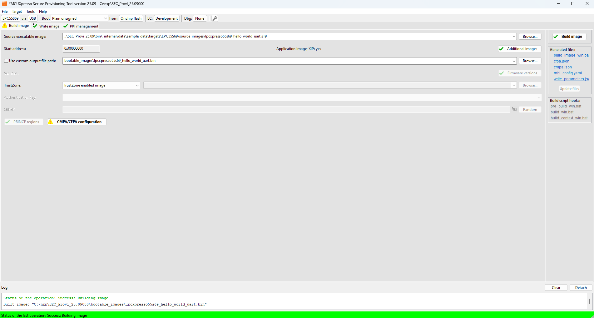
Fig. 23 SEC user interface#
Menu and settings#
This chapter gives detailed information about menu options and settings of the tool.
Title of the main window#
The main window title shows:
Asterisk (*), if the configuration is not saved on the disk (it is “dirty”)
Name of the tool
Path to the current workspace
Preferences#
User preferences are stored in the folder <user home>\.nxp\secure_provisioning_<version>\ and are shared for all workspaces. The preferences are backward-compatible, so for example SEC Tool v9 can load preferences from SEC Tool v8 if preferences for v9 do not exist yet. If no preferences are available, the SEC Tool starts with default values.
User preferences contain information about recently used files and workspaces, window sizes, locations, positions of the splitters, and options configurable in the Preferences dialog:
Timeout for communication re-established after reset (flashloader to be initialized) [sec] : Represents a delay (in seconds) after which the ROM bootloader or flashloader will be ready after reset of the processor. The real value may be affected by the configuration of your host. The selected value may affect the generated write script.
Maximal number of recent workspaces displayed in the File menu : Customize the maximal number of recent workspaces displayed in File > Recent Workspaces. Supported range 1 - 25. Default value: 9
Read current values after the OTP/PFR configuration is opened : Choose how the reading of device values on opening the OTP Configuration is handled.
The following options are available:
Never : Do not read the values automatically
Ask : Confirm the reading manually
Always : Automatically read device values
Preferred language for the tool : Select the language in which the tool will be displayed. Supported languages are English and Chinese.
The following options are available:
Default : The language is selected based on the language selected in the operating system. If the system language is different from the supported languages, English is used.
EN : Set the tool to English
ZH : Set the tool to Chinese
Save tool settings : Specifies when the tool settings must be saved to the disk.
It is possible to select one of the following options:
Automatically : It is the default value. The settings are saved if needed
On request only : The tool always asks whether to save the settings or not
Sound on error during configuration : If a new error is displayed in the configuration dialog, the tool notifies the user with a sound signal. The sound signal is OS-specific.
Password/key visibility at startup : Specifies whether the passwords and keys are shown or hidden at the SEC Tool startup. In the UI, the visibility can be controlled by the button, so this option configures just the initial value.
Check for the new version of the tool : Specifies how frequently the tool checks the availability of the new version during the start-up.
It is possible to select one of the following options:
Never : Never check; the feature is disabled
Daily : The check is executed once per day
Weekly : The check is executed once per week
Monthly : The check is executed once per month
Help NXP improve the tool by sending diagnostic data : If enabled, this feature allows the collection of diagnostic data to generate statistical insights into how the tool is used. This helps us enhance functionality and prioritize improvements. If disabled, no data are collected or transmitted.
Statistical data collection notice
To support continuous improvement of our software, we collect diagnostic usage data that include:
Frequency of tool and user interface feature usage
Operating system details (type, version)
Device configuration
Target device, boot type, boot device type, TrustZone status (enabled/disabled), connection type (USB, UART, and so on)
Trust provisioning method (Device HSM, EL2GO), debug authentication (enabled/disabled), signature provider (enabled/disabled), debug probe type
Although the types of data collected are clearly listed above, we explicitly confirm that the following are not collected:
Personally identifiable information (PII), such as names, email addresses, or contact details
User-generated content, including project files, source code, or any data stored on the user’s device
Location data or behavioral tracking is outside the scope of the tool usage
Sensitive project information (for example, fuses, cryptographic keys, file paths or file names)
All collected data are non-personal, not shared with third parties, and is used solely to improve user experience and guide feature development.
Custom text editor
: Allows specifying a custom text editor for opening and editing configuration files. A full path to the executable or system environment variables is accepted. A substring {path} will be replaced by the absolute path of the edited file.
Restricted data … : The data can be downloaded from the Secure Provisioning Tool home page, however, access to this package is contingent upon the execution of a Non-Disclosure Agreement (NDA). Among other, the data contains some trust provisioning firmware. The data are installed from a ZIP archive. SEC first verifies whether the selected data are compatible with the current tool and if yes, the data are copied into the subfolder in the user home directory. To start using the data, restart SEC.
Use restricted data from directory : Allows controlling whether the restricted data are used. The checkbox is enabled only if restricted data are installed. The option can be used to temporarily disable the installed restricted data.
Workspaces#
All files generated by the tool are stored in a dedicated folder structure called a workspace.
A workspace is a practical concept for operating with multiple boards, devices, or executables signed with different sets of keys. It is recommended to create a workspace for every project.
A workspace is always created for a specific device family (series of processors). Once created, it can only be used to modify the configuration of devices belonging to that family.
There are two types of workspaces:
Development workspace : The workspace is used during regular tool operation.
Manufacturing workspace : The workspace is used during manufacturing. See section Manufacturing workflow for details.
To create a development workspace, select File > New Workspace… or File > Import Workspace… from the menu bar. To create a manufacturing workspace, use command File > Import Manufacturing Package…. See New workspace creation for details.
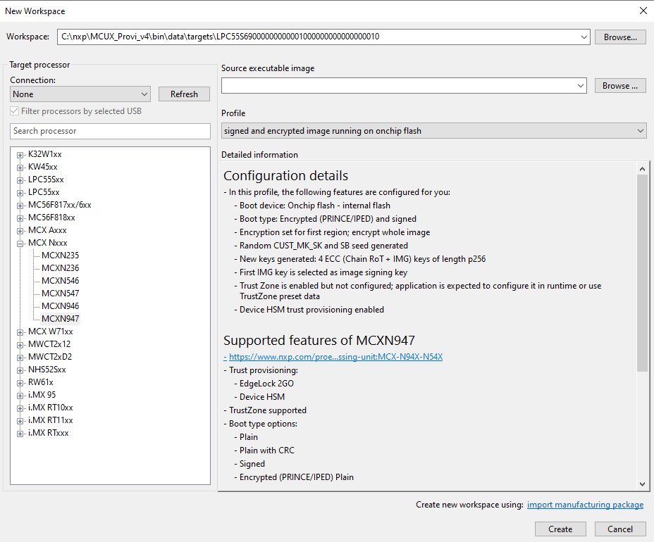
Fig. 24 Create a workspace#
To switch to a different workspace, select File > Select Workspace … from the menu bar and choose the path from the Open Workspace dialog. Another way to open the existing workspace is to double-click the appropriate settings.sptjson file in file explorer. It opens the tool with the given workspace.
To switch to a recently used workspace, select File > Recent Workspaces from the menu bar and choose from the list.
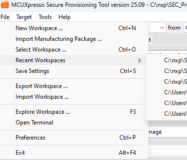
Fig. 25 Selecting a recent workspace#
Every created workspace contains multiple subfolders. Some of them are specific to device families. For the new workspace, most of the subfolders are empty; the files are generated or added by the user later.
backups/: Backup of old keys/crts after importing or generating new onesbootable_images/: Intermediate and final bootable images (nxpimage output). The no padding binary starts at the address IVT, while the regular binary includes everything from the beginning of the boot device.configs/: Generated configuration files, for example, OTFAD/IEE config file (YAML), BEE user keys config file (YAML), and the corresponding generated (BIN) files.crts/,keys/: Generated certificates and their corresponding keys.dcd_files/: DCD files included in the build image step.debug_auth/: Debug authentication files generated by the tool, configuration file for certificate generation (YAML), certificate request (ZIP), certificate (DC and ZIP), and authentication script.el2go/: Files for EdgeLock 2GO trust provisioninggen_bee_encrypt/: BEE user key files created during the build image step for XIP encrypted boot types. The keys are used to burn SW_GP2/GP4 fuses during the image write step.gen_hab_certs/: Output super root key table and hash (nxpcrypto output). The table is programmed along with the bootable image. The hash is programmed in platform fuses.gen_hab_encrypt/: DEK key files generated by the nxpimage utility. The DEK key file is used during write the image to generate the key blob for the encrypted HAB boot type.gen_scripts/: Temporary scripts for tool operation.hooks/: Hook scripts allow customizing build, write, or the manufacturing process. Hooks with prefix “pre” are executed before the script is executed. Hooks with “context” in the name are executed at the beginning of the script after the environment variables are defined. They can be used for environment variables redefinition. General hook files are called multiple times during the script execution. For details, see Build image, Write image, Manufacturing Tool.logs/: Log files; log.txt contains content/history of the Log view. The folder also contains logs from SPSDK command-line applications and from the manufacturing.root folder : Contains the following:
Last configuration of the tool in file
settings.sptjson.Build and write scripts.
Build and write JSON files containing all parameters used to generate the build and write scripts.
source_images/: Primarily intended as a folder to store input images provided by users. Also used by the tool to store input images, if input format conversion is needed.trust_provisioning/: Trust provisioning files (supported only if the processor supports trust provisioning)trustzone_files/: TrustZone-M configuration files (YAML, JSON, or BIN) used by nxpimage during bootable image generation step (nxpimage input).
New workspace creation#
To create a workspace, select main menu > File > New Workspace. The following options can be selected in the New Workspace dialog:
Workspace path : The folder where the workspace is created; use an empty or non-existing folder.
Connection : Connection that should be used in the new workspace for communication with the processor. If no connection is selected, a new workspace is created with the default connection for the processor.
Refresh button : Update the list of detected connections.
Filter processors by selected USB : When checked and the USB connection is selected, the device tree is filtered by the device family identified by USB VID/PID
Search processor : Filter processors from the processors tree. A substring of the processor, series, or board name can be used.
Processor tree : Displays processors matching the filter above. The processors are organized in folders by high-level processor category and series. If the default configuration is compatible with any evaluation board, the board name is displayed in brackets together with the processor name.
Source executable image : Chooses the input executable application image file. For more information about the input image format, see Source image formats. For the supported board, the tool contains sample applications that can be selected from the drop-down list.
MCUboot bootloader image : Allows users to configure the workspace to use the MCUboot bootloader. For more information about MCUboot, see MCUboot workflow.
Profile : Pre-defined settings that will be applied to the new workspace. It is recommended to start development with the default profile and verify the plain image works. For secure profiles, the Quick Fix from the toolbar will be applied to the configuration so there are no errors by default. It is also possible to create a custom profile, see Custom profile creation.
Boot device : Selection of a specific boot device type (optionally also with the boot device instance) that will be applied to the new workspace. This option is configurable only for the
Defaultprofile; otherwise, the boot device is specified in the profile. Auto-selection of the boot device is supported. When no source image is specified, auto-selection will use the default boot device type specified for the selected processor or board. When a source image is selected, auto-selection will use a boot device type based on the image start address. There is currently no validation of compatibility with source image and boot device type in case of manual selection.Detailed information : A panel with text information about configuration details and supported features. The configuration details section displays information about pre-configuration of the workspace based on the profile selection. The “Supported features” section lists the processor features that are supported by the tool.
When the workspace is created, the information is stored into the workspace root folder in the HTML format.
Sharing and copying workspaces#
It is recommended to store all used files in the workspace directory or sub-folders. The settings.sptjson file contains all paths relative to the workspace root folder, so if you open settings on another computer, you can still regenerate all scripts. The workspace can be a part of another project. Paths to the parent folder (including all its sub-folders) are stored as relative, but paths to other folders are absolute. It is recommended to use the File > Export Workspace dialog for sharing workspace.
In case the script must be executed on another computer without regeneration, it uses environment variables to specify the SEC installation directory and workspace. These environment variables can be specified externally, or if not specified, the default value is used. Workspace is detected automatically and an environment variable must be specified only if the script is copied outside the workspace.
The workspace can be exported using the Export Workspace dialog, select File > Export Workspace … from the Menu bar. The dialog box displays options for exporting the current workspace into a ZIP file with optional AES encryption.
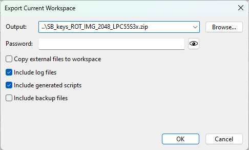
Fig. 26 Export Workspace#
The Export Workspace dialog allows selecting the following options:
Output : Path to the output ZIP file to be created. Any existing file will be overwritten.
Password : Optional password for a ZIP file encryption. Leave empty for no encryption.
Copy external files to workspace : Select this option to copy all external files (files located outside the workspace directory) into the exported workspace. A list of all external files is shown in the tooltip. All files will be saved in the
source_images/folder. Filename conflicts are automatically resolved to ensure that no file is overwritten. The current workspace and settings are not affected. The operation affects the ZIP archive only. The tool configuration is not affected. The option is not available if any file does not exist.Include log files : Select this option to include all log files in the exported workspace.
Include generated scripts : Select this option to include all generated scripts. The scripts contain an environment variable to specify the workspace the SEC installation directory, which is an absolute path. Regeneration of the scripts may still be needed.
Include backup files : Includes files from the “backup” sub-folder.
A warning message is shown when there are some absolute paths detected in the included files. A list of these files is presented as a tooltip.
Import workspace from the ZIP#
For importing the manufacturing package, select File > Import Manufacturing Package … from the menu bar.
For importing the workspace archive, select File > Import Workspace … from the menu bar.
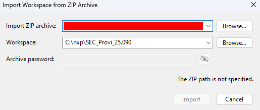
Fig. 27 Import Manufacturing Package or Workspace Archive dialog#
The Import dialog contains the following options:
Import ZIP archive : The path to the ZIP workspace archive.
Workspace : The target folder where the imported workspace is extracted; it is recommended to use an empty or non-existing folder.
Archive password : A ZIP password for encrypted archives. This field is enabled only when encryption is detected.
The dialog allows importing both workspace from the ZIP archive and manufacturing package. In both cases, the workspace is imported into a new directory (or empty directory). For the workspace import, the tool supports imports from older versions, but for the manufacturing package, the tool and the manufacturing package version must be the same. If the ZIP file is encrypted, write the correct password. For more information about the manufacturing process, see Manufacturing operations.
Custom profile creation#
A custom profile for New Workspace wizard can be created from any workspace using settings.sptjson. The profile is a subset of the workspace setting that is relevant for the profile. Profiles must be placed in the <install_folder>/bin/_internal/sample_data/targets/<processor name>/configuration_profiles folder to be offered as an option for the profile selection in the New Workspace dialog. To create a valid profile, manually specify these JSON fields:
is_profile : a flag identifying a profile setting, it must be set to true
profile_name : the name of the profile; this name is displayed in the tool and must be processor-unique
profile_description_introduction : the profile description in the natural language. It is displayed before the formatted profile description. This field is optional.
profile_description : should contain information what is set by the profile. It must be specified as a list of information.
Fields that should be removed from the profile settings:
write_image_settings, keys_management_settings, and connection have no meaning for the new workspace.
From build_image_settings, remove all fields that contain secrets that should not be distributed (such as dek_key, keyblob_key_id_int, sbkek, sb_seed) or fields that are irrelevant for the new workspace (source_image_path, dcd_path, ele_firmware_path, xmcd_path, tz_path, script_updated, updated)
The description of all fields can be found in the JSON schema settings_schema_##_##.json distributed within the tool installation files.
Toolbar#
The toolbar offers a quick selection of basic settings. The same commands are also available in main menu > Target.

Fig. 28 Toolbar#
Processor : Shows the chosen processor. Click the button to switch the processor. You can switch to a processor from the same device family for which the current settings are compatible. To select a processor from a different family, create a new workspace.
Connection (via) : Choose the connection to the target. The tool supports UART, USB-HID, SPI, and I2C connectivity. Click the button to customize connection details. For more information, see Connection.
Boot mode : Choose the type of boot. The list depends on the device capabilities of the currently selected processor.
Boot memory (from) : Click the button to open the boot memory configuration. For more information, see Boot memory configuration.
Life cycle : Allows the selection of the processor life cycle. Click the button to select from processor-specific life cycles; the selection dialog displays a short description for each option.
Trust provisioning type : Allows the selection of the trust provisioning type and enabling it for the trust provisioning operation. For details, refer to Trust provisioning.
Debug probe : Allows the selection of the debug probe connected to the computer; see Debug Probe Selection dialog.
Quick fix : The button allowing to resolve problems that are displayed on the build tab. Before the solver does any changes, the user is prompt to save settings. Once the quick fix is complete, a list of actions that were applied to fix the problems is displayed; the actions are also displayed in the log. It is recommended to review all changes carefully to ensure that the solution meets the expectations. Note: Some problems, such as missing external files, cannot be fixed by the “quick fix” solver.
Connection#
The Connection dialog allows you to select the connection with the target processor and test it.
The dialog is accessible from Target > Connection from the menu bar or the toolbar.
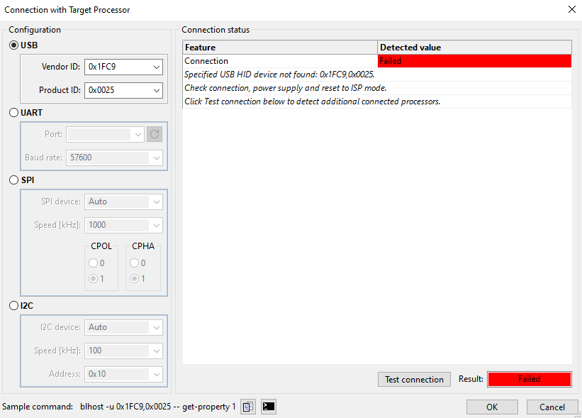
Fig. 29 Connection dialog with errors and proposed next steps#
It contains the following options (if supported for the processor):
USB : Specify USB-HID connectivity to the specified Vendor ID/Product ID pair.
UART : Specify UART connectivity through the specified port and baud rate. The baud rate is automatically detected by the bootloader when processing the initial ping. This means that the target processor must be reset after a new baud rate has been selected.
SPI/I2C : It is possible to connect with the processor using an SPI or I2C connection using the LIBUSB interface available on:
LPC-Link2. LPC-Link2 is present on several EVK boards, however, to connect via SPI you must use jumper wires to connect with the processor.
Before starting the Secure Provisioning Tool, it is necessary to download and install USB drivers from the product pages listed above. It is possible to configure the following connection parameters:
SPI/I2C device : The device is specified using a USB Path. The default value in the connection dialog is “Auto”, which means if there is just one device connected to the computer, it is selected automatically. The details about the USB Path format can be found in the SPSDK documentation.
Speed [kHz] : Communication clock frequency in kHz.
CPOL, CPHA : Signal polarity and phase; see SPI specification for details.
Address : Address of the I2C device.
Crystal frequency [kHz]
: Frequency of the external crystal. It is used to configure communication speed with the processor. Currently it is used only for lpcprog tool.
Use the Test connection function to verify that the device can be properly accessed with the given configuration. To ensure successful detection of the processor with Test connection, make sure of the following:
The board is correctly powered up
The board is properly configured to ISP (In-System Programming) mode
The board is connected to the computer
The connection dialog detects the following parameters:
Connection : Status of the selection of a communication device (USB or serial port) or a USB path for the SPI/I2C connection
Mode : Communication mode ROM bootloader or flashloader application.
Processor : Match if the connected processor matches the selected one, No match otherwise. This feature allows finding a mistake when the SEC Tool is communicating with a wrong board. This function is not 100% reliable as there is not enough information to identify each processor.
Life cycle : Life cycle that was detected in the connected processor.
Silicon version : Displayed only if the connected processor is of an older version. When the old revision is detected, the connection test results in a Failed state. All known issues related to this version are mentioned in the tooltip.
Other : There might be displayed other processor-specific parameters.
The following connection results are possible:
Not tested yet: Use the Test connection button to run tests.OK: Connection successfully established.FAILED: Connection tests failed. For details, see Connection status. For more information about the failure, it is possible to use SEC in verbose mode and find details in the console view.
At the bottom of the connection dialog, there is the Sample blhost/sdphost/lpcprog/nxpuuu command that allows running the corresponding SPSDK command-line tools with specified arguments. The first button copies the command with arguments into the clipboard. The second button opens a terminal where the command can be executed.
Boot memory configuration#
The Boot Memory Configuration dialog allows selecting and configuring a boot device. The dialog contains the following configuration parts:
Boot memory type : This part allows selection of the boot memory type, and optionally, instance.
Predefined template : This part allows selection of the boot memory configuration template. The list is specific for each memory type and contains memories where some are available on NXP evaluation boards. After opening the boot memory configuration dialog, the option contains the previously selected memory (if values were not changed), or is empty, the first item in the drop-down menu is a memory used on the evaluation board (if applicable). Memory configuration templates that are marked as verified were tested on hardware.
User configuration : This part allows loading or saving the configuration to the selected file. It might be useful for reuse of the configuration for another project or sharing the configuration with colleagues.
Protected area : This part allows specifying the memory area that must not be changed by the SEC Tool. If the tool tries to erase or modify the selected memory area, a confirmation dialog is displayed. It might be useful for protection of the custom data in a boot memory. Specify comments/reasons, because it will be displayed as part of the confirmation message.
Boot memory configuration parameters : Configuration of the memory, these parameters are specific for each memory type.
Comment : The description of the boot memory that contains information if the predefined template was applied
Test the configuration : This button is used to test the current memory configuration with the connected processor/board. The test consists of two steps: read test (whether the memory can be read) and bootloader test that verifies the memory configuration using the blhost list-memory command.
Convert to Complete FCB : This option is available for SPI NOR only. The button allows converting a simplified SPI NOR configuration into a full “Flash Control Block” (see SPI NOR)
SPI NOR#
SPI NOR flash can be configured in two ways:
by using the flashloader/ROM based simplified configuration (two 32-bit words)
by using the complete Flash Control Block (FCB binary, 512 bytes)
For a simplified configuration, the user can modify the values suggested in the dialog box. To create your own FCB from SEC Tool, use the Convert to complete FCB button in the bottom-right corner. It opens the Convert To Complete FCB dialog box that allows to convert existing simplified configuration into complete configuration using the connected processor. A simplified device configuration is written to an SPI NOR flash device and read back while the original data are preserved. When the conversion process is complete, it creates a .bin file in the desired location, given by the path to the FCB file.
The Convert To Complete FCB dialog offers a checkbox to use the created FCB binary file as a SPI NOR/user FCB file. If unchecked, only the conversion is done.
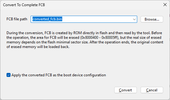
Fig. 30 Convert to Complete FCB dialog#
FCB can also be created in MCUXpresso IDE by adding the FCB component into Peripheral Drivers in Peripherals tools, where the full configuration can be specified.
When the complete FCB is specified in the boot device configuration, the user can specify two separate FCB files. The FCB for runtime is used for flash configuration during the processor boot. The FCB for write is used for flash configuration for programming the application.
Serial downloader#
The serial boot provides a way to download a boot image to the chip and execute the image. In this boot mode, a host PC/device can communicate to the ROM bootloader, using the serial downloader protocol. The SEC Tool allows execution of the image in internal or external RAM. It might be useful to run the application on a flashless processor.
The write script contains both the provisioning of secure assets to the processor and the loading and the execution of the application in RAM. During manufacturing, the application is not loaded.
On-chip RAM#
The SEC Tool allows creating images executed in internal RAM, which might be useful for chip (re-)configuration or executing a diagnostic test. For this boot memory, the write script writes the application into the processor and intermediately launches it. If the chip is secured, the application is written and launched via the SB file.
Note: The SB file could also be used for recovery flash.
Trust provisioning#
The Trust provisioning dialog allows selecting a processor-specific trust provisioning type and enabling it for the trust provisioning operation.
The SEC Tool supports the following trust provisioning types:
Device HSM : the secrets are encrypted using a key stored in a processor. It is the same for all processors in the series.
EdgeLock 2GO : the secrets are stored in the NXP cloud, on the EdgeLock 2GO server.
Device HSM provisioning#
There are two types of device HSM provisioning:
The device HSM is directly supported in ROM. In this case, there is no need for extra firmware.
There is extra firmware needed for the following use cases:
i.MX RT5xx/6xx where the device HSM is optional. For details on how to enable it, see RT5xx/6xx device HSM provisioning.
RW61x processors where the device HSM is mandatory for secure boot types are partially supported in ROM. This firmware is distributed in tool data.
To successfully build an image with Device HSM enabled, the processor must be connected and selected in the Connection dialog. It is not required only when there is already an image built with Device HSM and the settings are the same.
EdgeLock 2GO trust provisioning#
EdgeLock 2GO is NXP Semiconductors’ cloud‑based security and provisioning platform designed to securely install keys, certificates, and other credentials into the IoT devices.
There are two EdgeLock 2GO flows supported:
EdgeLock 2GO with device ID: the secure objects are retrieved from the EdgeLock 2GO cloud server during the provisioning process
EdgeLock 2GO per product type: the secure objects are retrieved from a server in a batch database and provisioning can be executed without connection to the cloud server (offline)
Other configuration controls for accessing the assets on the EdgeLock 2GO cloud server:
API key - user-specific HEX key granting access to the server. For details, see API key to access EdgeLock 2GO server.
Device group ID - the identification number of the device group on the EdgeLock 2GO server that contains all the secure assets. On the EdgeLock 2GO server, it can be found under Devices > MCU & MPU.
12NC - hardware product unique identification. On the EdgeLock 2GO server, this can be found within the information about the device group.
Secure objects address - address in the flash memory where the secure objects are stored during provisioning.
Server URL - URL of the EdgeLock 2GO REST API server. Use an empty string to apply the default value.
The Test button allows verifying a connection to the server.
Product Batch Database panel allows to generate and download a database of secure objects from the EdgeLock 2GO server and use it for offline per product provisioning flow. For details, see Database with secure objects for EdgeLock 2GO per product type.
#devices - number of processors to be included in the batch database
#batches - number of batch databases to be generated
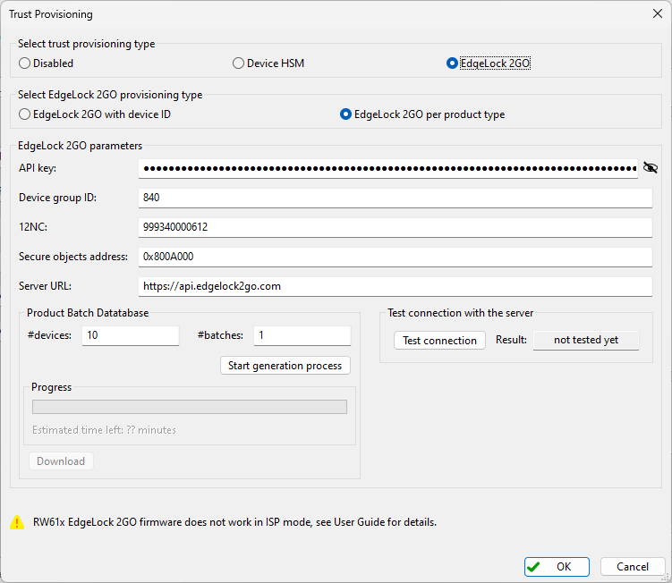
Fig. 31 EdgeLock 2GO trust provisioning#
Debug Probe Selection dialog#
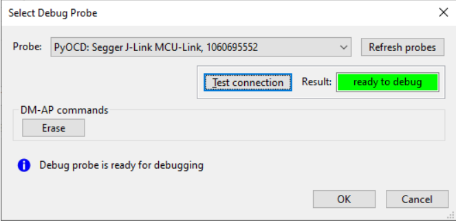
Fig. 32 Debug Probe Selection dialog#
The Debug Probe Selection dialog allows users to:
Select a debug probe
Use a test connection with the given probe
Erase the processor flash (if supported in the processor via the debug probe API)
When the dialog is opened, the probes connected to the computer are detected. It is possible to rescan the probes anytime later again using the Refresh probes button.
There are two options for selecting a debug probe:
The probe can be selected using a type and serial number. This is recommended if you have several probes of the same type.
The probe can be selected only by the type (such as MCU-Link, J-Link, LPC-Link2). This allows switching the boards without re-configuration. This selection cannot be used if two probes of the same type are connected at the same time.
The Test connection button provides information on whether the debug can be started for the selected debug probe. The possible results are:
ready to debug - if the debug probe and the processor are ready for debugging
no debug - if the connection with the debug probe was established, but the processor cannot be debugged; in this case ensure that the probe is properly connected and the processor is running (not ISP mode)
FAILED - if the connection with the debug probe failed
The Erase button allows erasing the internal flash (mass erase). See the reference manual for processor-specific details.
Build image#
In the Build image view, you can transform an application image into a bootable format compatible with the selected processor.
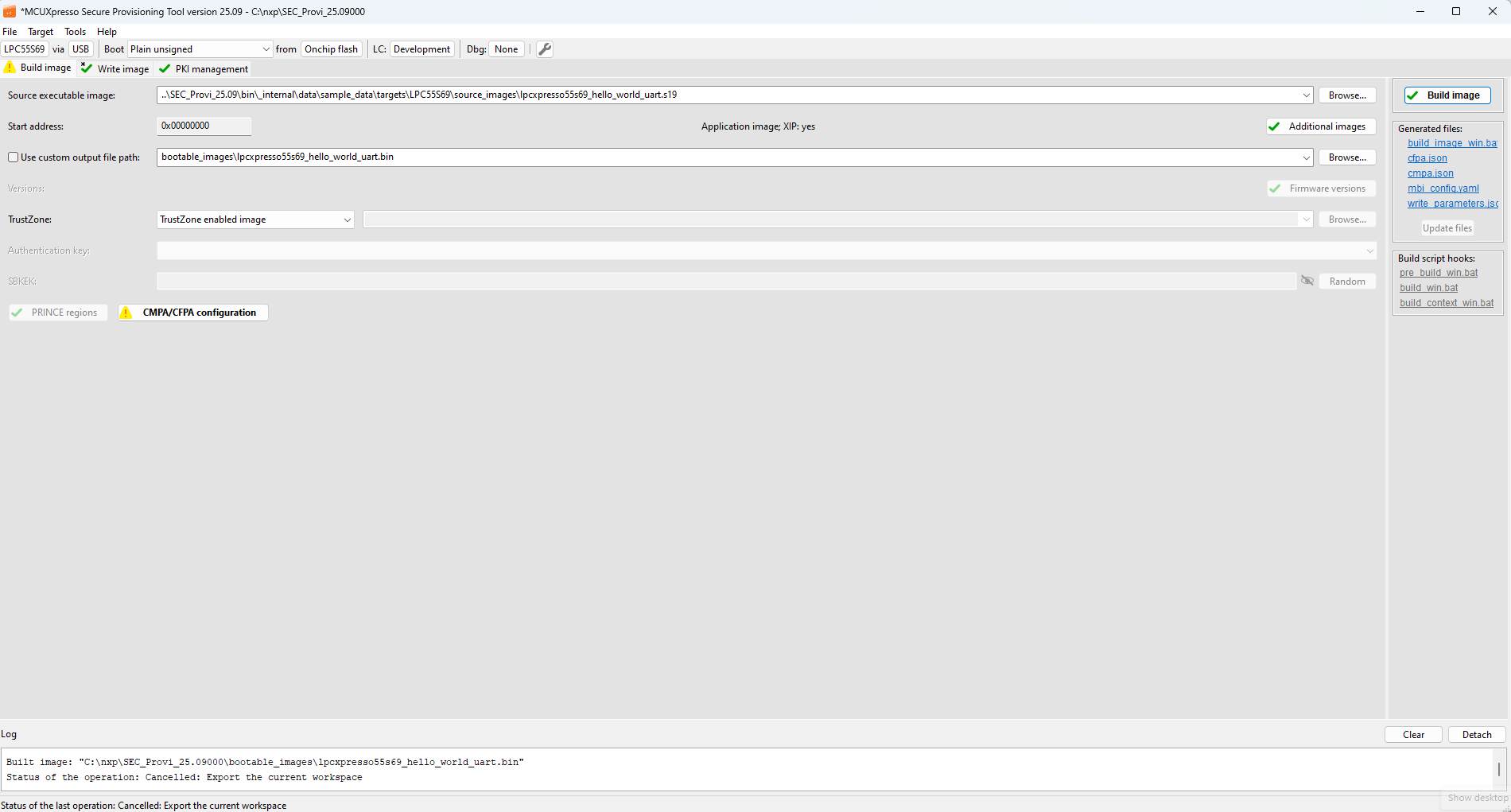
Fig. 33 Build image (LPC55Sxx)#
Controls on the Build image view#
Source executable image : Chooses the input executable file. For more information about the input image format, see Source image formats.
Start address : The base address of the image. It is editable only to a binary image. For ELF and S-Record and HEX files, it is detected automatically.
Application/Bootable image and XIP : The label provides the following information about the selected source image:
whether it is an application or a bootable image.
whether the selected source image is built as “eXecuted In Place”, and will be executed from the boot memory, where it is stored. If not, the image must be copied to RAM before the execution. The information is derived from the starting address of the image and compared with the memory address of the selected processor, so the result might not be correct if the selected image does not match the selected processor.
Additional images : Opens the configuration dialog for the Additional User/OEM Image. For i.MX 9x devices, this control is called Bootloader images and opens the same configuration dialog, named Bootloader images. For details see chapter Additional and bootable images dialog.
Memory map : A small button next to the Additional images button, on the right side, allows opening the memory map window. The window contains three columns:
First column shows the physical memory map on the device; for multicore devices, the memory is displayed for the booting core. The vertical scale is exponential, so the smaller blocks are properly displayed.
Second column contains regions used to store data for booting (blue color) and system regions (gray color).
Third column extends the second column with regions used in runtime; if some images are loaded to RAM during the boot process, these RAM locations are displayed in green color.
The window is dynamically refreshed after each change, so it can be opened all the time, if needed. This can be helpful to verify, whether the image is installed and built at the right location in memory.
Note: If the tool configuration is not correct, the displayed info might be wrong.
Use custom output file path : Name of the generated bootable image file and its location. If not specified, the tool names the image based on the input. The file extension is specific for a processor and a boot type, it is either BIN for bootable images or SB for secure-binary capsules.
Image version : Version of the bootable image. Typically, it is used for dual image boot. The image with the higher image version is booted first.
Dual image boot : Opens the configuration window for dual image boot. Image can be written to the base (Image 0) and/or to the remapped (Image 1) space of the flash, each of the them has its own image version. See the reference manual, how the image is selected; usually the ROM then uses the image version to select the latest image to boot and if the latest image boot fails, the old image is used to boot again.
Firmware versions : Opens the configuration dialog of Firmware version(s). The firmware version allows setting the anti-rollback protection. For details, see Firmware versions.
XMCD : Allows enabling the External Memory Configuration Data feature. XMCD is needed for comprehensive or feature-rich applications requiring large capacity of RAM (on-chip RAM is not enough). Either a YAML or BIN configuration file can be provided or XMCD simplified configuration can be prepared in XMCD configuration dialog. (for details, see the description of the –xmcd-cfg CLI parameter).
DCD (Binary) : Selection of what Device Configuration Data must be included in the bootable image. The option From source image can be used only if the source image contains DCD. The DCD enables early configuration of the platform including SDRAM. MCUXpresso Config Tools can generate a DCD in a compatible format. If the target processor does not support DCD files, the checkbox is disabled. For more information, see Creating/Customizing DCD files.
TrustZone : Allows you to enable TrustZone features. The following selection is possible:
TrustZone disabled image - Disables TrustZone. This option is not supported for some processors.
TrustZone enabled image - Enables TrustZone with the default configuration preset in the processor.
TrustZone enabled image with preset data - Enables TrustZone with custom TrustZone-M data. JSON and BIN file formats are supported. JSON data can be generated in and exported from the TEE Tool of MCUXpresso Config Tools. BIN file is created by the
nxpimageutility. For more information, see TrustZone configuration file.
Authentication key : Signs the image with the specified key. The key can also be used for the authentication of the SB file. This option is only applicable to authenticated and encrypted boot modes and offers a selection of keys generated in the PKI management view.
Key id : The keyblob encryption key identifier is used in the encrypted (AHAB) boot type
AHAB/HAB encryption algorithm : Selection of AHAB/HAB encryption algorithm used in the encrypted (HAB), authenticated, or encrypted (AHAB) boot types.
Key source : A key source for signing the image.
User key : For the OTP key, the source master key is used to derive other keys. For the PUF KeyStore, the user key is used to sign the image. Only available for Plain signed boot types.
SBKEK, SB3KDK, or CUST_MK_SK : A key is used as a key-encryption key to handle an SB file. Only available for secured boot types. For RT5xx/6xx, it is only enabled when the key source is KeyStore. For LPC55Sxx devices, the key store is initialized only once in the device life cycle and after that, any change in SBKEK will cause failure to load the SB file into the processor. For more information, see PFR and PUF KeyStore. OEM seeks a hex key used to randomize the creation of the SB file with the CUST_MK_SK key.
Configuration dialogs : The following configuration dialogs are available on the Build image view:
XIP encryption (BEE user keys) : Opens the configuration dialog of XIP encryption user keys. Option enabled only for XIP encrypted (BEE user keys) authenticated and XIP encrypted (BEE user keys) unsigned boot types.
XIP encryption (BEE OTPMK) : Opens the configuration window of BEE with the OTP Master Key. The option is enabled only for XIP encrypted (BEE OTPMK) authenticated boot type.
IEE encryption : Opens the configuration dialog of IEE encryption. The option is enabled only for IEE encrypted boot types.
OTFAD encryption : Opens the configuration dialog of OTFAD encryption. Option enabled only for OTFAD encrypted boot types. For RT10xx devices, the button name is XIP encryption (OTFAD user keys).
XIP encryption (OTFAD OTPMK) : Opens a configuration window of OTFAD with OTP Master Key. The option is enabled only for XIP encrypted (OTFAD OTPMK) authenticated boot type.
PRINCE/IPED regions : Opens a configuration window for encrypted PRINCE/IPED regions allowing specifying which flash regions will be encrypted.
OTP/PFR/IFR/BCA/FCF configuration : Opens OTP/PFR/IFR/BCA/FCF configuration.
Generated files#
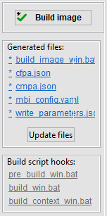
Fig. 34 Build image panel#
There is a build panel with the Build image button and a list of generated files on the right side of the Build image view. The Build image button updates all files and executes the build script. The icon on the button displays an asterisk (*) called “dirty flag” if the build script is not updated or is not successfully executed. The same indication is also displayed in the Build image tab.
The generated files below are displayed as clickable links, and the file content is displayed if you click them.
Each file contains an icon representing its status, see the following table for details.
Icon |
File status description |
|---|---|
|
The file status is being updated. It is updated on the background with some delay, so it might take a couple of seconds before the real status is displayed. |
|
This icon is displayed if there is a problem and the file cannot be generated. |
|
The file either does not exists or it is not updated and needs to be re-generated. The changes in the file are displayed in the tooltip for the icon, unless the file is binary or the changes are too large. |
|
The file is up to date. |
|
The file is locked. Locked files are not re-generated. Instead, the tool generates a file with the |
|
This icon is displayed on the right side of the file name in case the file must be uploaded to the EdgeLock 2GO server. |


The Update files button allows updating all files without the execution of the script.
Build script hooks#
Build script hooks are displayed in the Build image panel below the generated files. Hook scripts are called before or during the build script execution. The gray label means that the file does not exist in the workspace yet. After clicking, a new file is created with the content from the example and opened for modification. If the file exists, the label is blue and after clicking the file is opened. For details, see Script hooks workflow.
Source image formats#
SEC supports several formats for source image: ELF, HEX, BIN, or SREC/S19 (S-record). The image format is then unified into the format required by the build script, and this conversion is done inside SEC (the prior build script is called).
The SEC Tool partially parses the image to retrieve the entry point, to detect whether the image is XIP and validate the target address. In the S19 file format, the entry point can be listed explicitly, while for the other formats the entry point is retrieved from the interrupt vector table (so the interrupt vector table must be at the beginning of the application image).
For some processors, MCUXpresso SDK examples contain a bootable image including FCB configuration. The SEC Tool supports splitting of the bootable images into pieces (FCB, DCD, XMCD sections), and reusing the parts to build a new bootable image. Once a bootable image is selected and the parser accepts the image, the tool offers to reuse specific parts and if confirmed, the configuration is updated.
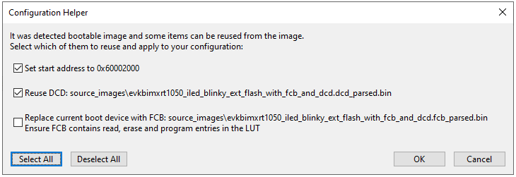
Fig. 35 Configuration Helper#
Note: For i/MX RT118x processors, SEC Tool generates the bootable image in SPARSE format (*.simg), however this format is not supported for the source image.
Additional and bootable images dialog#
Additional images and Bootable images dialogs are based on the same GUI controls; however, the functionality is slightly different:
Additional images dialog allows the user to specify up to 8 user images that will be written into boot memory together with the application.
Bootable images dialog allows specification of up to 16 user images as the processors support primary and secondary container sets. This dialog does not contain the application source image.
The configurable options (columns) depend on the image format. They are different for AHAB images and the other processors.
The configuration is represented as a table, where each row represents one user image. Columns represent configurable features for each image. A description for each feature can be found in the tooltip. The last image is reserved for the application executable image, which is automatically updated according to the build tab. The order of any image, except for the application executable image, can be changed by the up/down arrow in the right upper corner.
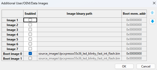
Fig. 36 Additional User/OEM Images configuration#
The examples of typical usage of the additional images:
add an image for the second core
add an application image for the secondary bootloader
add a binary data from an external file
Firmware versions#
The Firmware Versions dialog allows configuring anti-rollback protection. In the Firmware Versions dialog, specify Secure and Non-secure firmware versions for the image and optionally a value for CFPA or fuses that are used for anti-rollback protection as a minimal version.
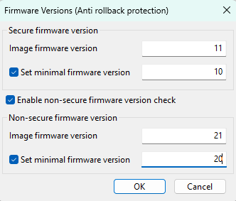
Fig. 37 Firmware versions dialog (LPC55S36)#
Each panel (Secure firmware version and Non-secure firmware version) is used for a specific firmware version. These versions are checked during the SB file or AHAB image uploading against values in CFPA or against fuse values (the uploaded version must be equal to or greater than the appropriate value in the CFPA or fuses). The Secure firmware version specifies the secure image version checked during booting by the ROM.
Specifying values for the Non-secure firmware version is optional and can be enabled or disabled. The non-secure firmware version panel is visible only for processors that support the Non-secure firmware version.
Image firmware version. This version is included in the bootable image and/or it is checked in the SB file or AHAB image. The value must be greater or equal than the minimal firmware version.
Set minimal firmware version. Specify the minimal firmware version stored in CFPA or in fuses for enabling anti-rollback protection. The value must be equal to or smaller than the specific image firmware version. If the value is not specified, it can be specified in the OTP/PFR configuration dialog or the default value can be used.
XMCD configuration dialog#
The configuration dialog allows customizing parameters for simplified XMCD. These parameters are specific for the selected XMCD memory interface, it can be either:
FlexSPI/XSPI interface for the HyperRAM/APMemory or
SEMC interface for SDRAM
The XMCD configuration dialog can be reached by the XMCD Edit button on the Build image view when FlexSPI/XSPI RAM or SEMC SDRAM is selected.
The Import button allows importing simplified configuration from a YAML or binary file. The Reset to defaults button allows returning to default settings.
TrustZone configuration file#
TrustZone and related features of the ARM processors can be pre-configured by data from the application image header at boot time instead of setting the registers from the application code. TEE (Trusted Execution Environment) tool from MCUXpresso Config Tools allows you to export the TZ-M preset data for use in SEC Tool. Follow these steps to modify the existing example application, export the TZ-M file and add it into the application image.
To create, export, and import a TrustZone file, do the following:
Open an SDK example:
From MCUXpresso IDE:
In the Quickstart panel, select Import SDK example(s)….
Select the example to import.
In Project Explorer, open the context menu of the imported secure project.
From MCUXpresso Config Tools:
On start, select Create a new configuration and project based on an SDK example or hello world project.
Clone one of the TrustZone enabled (secure) projects.
Open the TEE Tool:
In MCUXpresso IDE: in the menu bar, select MCUXpresso Config Tools > Open TEE.
In MCUXpresso Config Tools: select the TEE tool from the Config Tools Overview.
In Security Access Configuration > Miscellaneous, use the Output type drop-down list to select ROM preset.
Configure security policies of memory regions as you see fit (for details, see User Guide for MCUXpresso Config Tools (Desktop) document GSMCUXCTUG
In the menu bar, select File > Export > TEE Tool > Export Source Files.
In the Export window, specify the JSON file download folder and select Finish.
Remove the BOARD_InitTrustZone() call from the SystemInitHook(void) function and tzm_config.h include located in the main application file (for example, hello_world_s.c)
Alternatively, basic TZ-M-preset JSON data included within the SEC layout can also be used as a starting point template for further modifications of TrustZone pre-configuration. Device-specific template files are provided in the sample_data\targets\<processor>\trust_zone_template.json
TrustZone templates provided in SEC Tool:
The TrustZone template format v1 contains all registers/options with default preset values. As SAU and AHB are disabled in the template, the template is expected to be customized before use.
The TrustZone template format v2 contains a list of commands for register initialization. The template provides a description of the YAML format and is expected to be modified before it is used.
After the JSON file has been downloaded, you can import it in SEC:
In the menu bar of SEC, select File > Select Workspace … and choose a workspace. Alternatively, create a one by selecting File > New Workspace ….
In the Build image view, switch the Boot type to Signed or Unsigned with CRC.
Use the TrustZone pre-configuration drop-down list to select TrustZone enabled image with preset data.
Click Browse to navigate to the location of the stored JSON file and select Open to import it.
It is possible to use YAML format instead of JSON to import TZ-M preset data into SEC.
OTP/PFR/IFR/BCA/FCF configuration#
The configuration dialog allows configuring:
One-time programmable fuses
CFPA and CMPA pages from Protected Flash Region (PFR)
ROMCFG/IFR page from Information Flash Region (IFR)
Bootloader Configuration Area (BCA)
Flash Configuration Field (FCF)
Use the configuration dialog to:
Review the configuration prepared by SEC
Read the current configuration from a connected processor
Customize the configuration
Lock the configuration (this feature is available for some fuses only)
In the OTP (One Time Programmable) Configuration, the configurable item is called a fuse. In the PFR (Protected Flash Region), BCA, FCF, and Information Flash Region (IFR) Configurations, the configurable item is called a field. The content of the dialog depends on the selected processor.
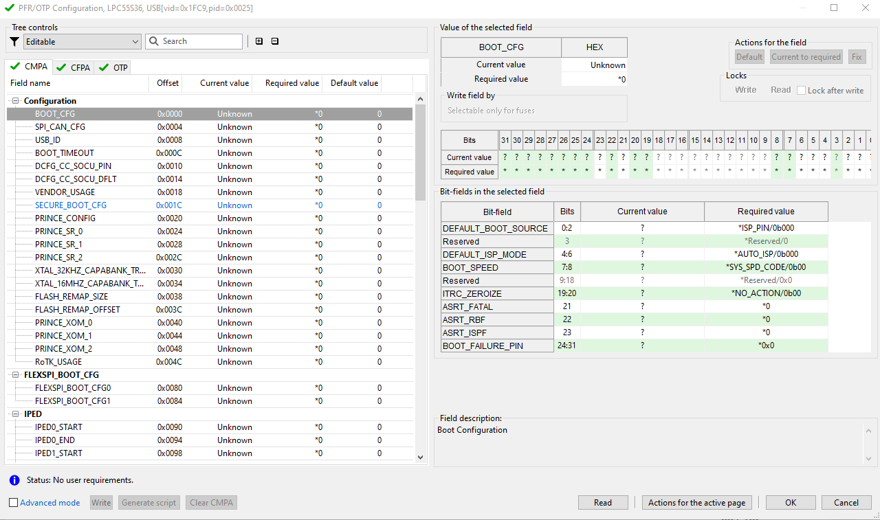
Fig. 38 OTP Configuration#
Primarily all changes in the configuration dialog will be applied as part of the write script - except for Advanced mode.
The configuration window contains three main areas:
Table of all fuses/fields (generally called items) on the left-hand side
Detailed information about the selected fuse/field on the right-hand side
Buttons bar in the bottom of the view
The width of the two main areas can be adjusted using the splitter.
Table of all items#
PFR Configuration supports two pages: CFPA (Customer In-field Programmable Area) and CMPA (Customer Manufacturing/Factory Programmable Area). The IFR Configuration supports one-page called either ROMCFG (ROM Bootloader configurations) or IFR. Each page represents a separate list of fields organized in a tree. In OTP Configuration, all fuses are displayed in a single tree. The items in the tree are organized into logical groups. The tree of all items is displayed in form of a table, with the following columns (a column might not be displayed if the feature is not available for the processor):
Name : Human-readable name of the item. Some names may not be public and are available as a restricted data package. See the section about restricted data in Preferences.
Offset or shadow : Offset of the item address or offset of the shadow register address
# : Index of the item (parameter for blhost to access the fuse)
R/W/O : Status of read/write/operational locks retrieved from the processor. For more information, see Locks.
Current value : The current value of the item read from the processor (hexadecimal)
Required value : The hexadecimal value required by SEC or by the user. Values preset by SEC are highlighted in blue and can be modified only in Advanced mode.
Default value : The default value of the item (hexadecimal) - after reset value.
Tree-filtering toolbar#
It is possible to filter items displayed in the tree. There are predefined filter types in the dropdown list with a description in the tooltip. It is also possible to search for an element by name using the text box.
The toolbar also contains two buttons allowing to expand or collapse all groups.
Item editor#
In the right part of the dialog, the following details are displayed for the selected item:
Table with the current and required item value as a hexadecimal number.
Current state of the read and write lock.
Selection, where the fuse will be written (see Burn fuse/write field).
Table with current and required item value as a binary number.
Table with current and required item value as bit-fields value (only if the item is split to bit-fields).
If the value is longer than 32 bits, there is the HEX value editor instead of the two tables listed above.
Description of the selected object (group of items, fuse, field, bit-field).
Read from connected device#
Before you start the OTP/PFR/IFR/BCA/FCF Configuration tool, it is recommended to check in the Connection dialog if the board is connected to the host. If the target device requires a flashloader (RT10xx, RT116x/7x, and RT118x), it is recommended to click Start flashloader in the Write image view to ensure that the communication with the device can be established.
After the Configuration tool is open, it will offer to load current fuse values from the processor. This feature is optional and can be done also anytime later using the Read button. The Preferences dialog contains an option to configure the initial read operation.
The read operation consists of the following steps:
Read locks to find which fuses are readable
Read current fuse values
Detect individual write locks (if applicable for the processor, see Locks for details)
Required value#
Items that must be written based on a selected configuration (for example contains preset value), are highlighted in blue. The remaining items, by default, either do not have any required value - displayed as * (asterisk) OR if default value is applied, they are displayed as *<value> (for example *0). The required value for these items can be specified:
As a 32-bit hexadecimal number
By bits. Click the value in the second row of the Bits table to toggle the bit, double-click to remove the requirement from the bit.
Per bit-field (only if the register contains bit-fields)
For some bit-fields, the value is selectable from a drop-down list; otherwise, it is specified as a decimal or hexadecimal number (with 0x prefix).
For items wider than 32 bits the value can be specified only as a HEX string. HEX string represents a sequence of bytes in the order as they will be stored in the memory.
Burn fuse/write field#
In the OTP/IFR configuration, it is possible to select the source where the fuse is burnt or the field is written:
Write a script
SB file that writes the application image
Provisioning FW can be either the device HSM SB file or the SB/BIN file used during provisioning (it depends on the processor).
The available options depend on the configuration, so for example if shadow registers are used, no other option is enabled.
Locks#
Locks are available in OTP Configuration to lock fuses. A lock block specifies an access restriction to the fuse - usually a read or write restriction. The locks must be programmed at the end of the development cycle when the rest of the configuration is already stable and tested and will not be changed. Locks are also used in IFR ROMCFG configuration. Here, the lock block specifies a write-access restriction to the ROMCFG block as each 16-byte block can be written only once. Similarly, the locks are also used in IFR configuration. Here, the lock specifies the write-access restriction to the IFR field as each 4-byte field can be written only once.
Two types of LOCKS are supported in SEC:
Global : Configured in a separate fuse usually called LOCK. The configuration is applied to several other fuses or shadow registers. READ, WRITE, or OPERATION locks exist, each type blocks the corresponding access to the fuse.
Individual write locks : For some processors, it is possible to apply a write-lock for a single fuse. Also, some fuses can be written only once and a write-lock must be applied. Both these features are presented as Lock after write checkbox, see description below. The Lock after write checkbox is also used to indicate a write restriction to the ROMCFG block or the IFR field.
The status of all locks is updated during the Read operation. The status is displayed in the fuses table, specifically, in these columns:
R : Display status of read lock for the fuse
W : Display status of write lock for the fuse (combined status of global and individual write lock)
O : Display status of operation lock for the fuse
The following icons are to represent the lock status:
Icon |
Description |
|---|---|
No icon |
The fuse does not support a corresponding lock. |
|
Lock status unknown |
|
Fuse access unlocked |
|
Fuse access is locked |


Lock after write checkbox is dynamically enabled or disabled based on the selected fuse.
Individual write-lock is not supported for selected fuse - checkbox is disabled and unselected
The fuse must be locked after the first write - checkbox is disabled and selected
Individual write-lock is optional - checkbox is enabled
For fuses configured to turn on individual write-lock, the following icon is displayed in the Required value column in the fuses table:
Icon |
Description |
|---|---|
|
Fuses configured to turn on individual write-lock |

On RT116x, RT117x, and RT118x devices, the lock after write status cannot be detected, so the fuse might be displayed as unlocked even if it was already locked.
Lock validation
OTP Configuration reports a warning in the case the write-lock for the fuse is on and the fuse value is not fully specified.
Calculated fields#
Some registers or bit-fields contain a value that is calculated using the value of another bit field. For example:
One item may contain the inverse value of another item
One-bit field contains the CRC of other bit-fields of the item
This feature is supported in Configuration as validation, the error is displayed in the case the calculated value does not match or the source value for the calculated item is not specified. See the following chapter for details about validations and problem resolutions.
Validation and problem resolution#
The configuration provides validation of the current and required values and the problems are indicated by the icon in the window title, in the tree, and for required value, if the item is selected, in the details section, in all editors.
In the BITS editor, the problem is displayed only for bits affected by the problem. It allows fixing the problem easily by clicking the affecting bit value (for example, inverting the required value of the bit).
For all errors in a required value, it is possible to use the Fix button. This button fixes all errors within the selected item. Ensure that you review the changes applied by the quick fix to confirm that the updated value meets your expectations.
Note: Specific OTP/PFR fields are used for the transition of the device through its life cycle, granting conditional or locking down access to various debug resources in the device once programmed. As the best practice, it is recommended to program these registers once the secure boot has been verified to be functional. Incorrect values in these fields may render the platform nonfunctional or no longer accessible for recovery. On some platforms, these registers include special “valid” semantics - for example, on the LPC55Sxx processors, the DCFG_CC_SOCU_PIN and DCFG_CC_SOCU_NS configuration fields include bits that must be programmed as the inverse of all the other fields in the register for the configuration to be valid. The Fix problems button enforces this constraint only if the register contains a non-zero value - that is, an explicit user configuration of the register has been detected.
Advanced mode#
By default, it is recommended to apply the modified configuration into a workspace settings file and the Write script, so it is applied together with the bootable image. However, sometimes it might be necessary to burn a single fuse value, in which case you can use the Advanced mode. The Advanced mode is designed for standalone usage of the Configuration tool and allows you to:
Write a required value directly to the connected processor (see Write/Burn)
Generate the script to write the required values
Modify all required values, even the ones preset by the SEC tool
Clear CMPA page; apply default values to the whole CMPA page
Additionally, the reserved items values are read from the connected processor in this mode (most likely useful to NXP engineers only).
The Advanced configuration is not expected to be applied to the write script, so the OK button is disabled. The Export button can be used to store the created configuration into an external file.
Note: Advanced mode is not needed for normal workflow supported by the SEC Tool, it should be used only for the use cases not supported by the tool.
Write/Burn#
The Write/Burn operation burns all required values into the connected device including all locks. The burn operation consists of the following steps:
Read current values from the processor
Update validation problems
Generate write/burn script
Execute the write/burn script
Bear in mind that the burn operation is irreversible. It is recommended to:
Double-check all values being burned
Double-check all items being locked
Double-check all problems reported by the configuration
Generate write/burn script and review the content
There is a difference between Burn and Generate Script:
The Burn operation is optimized for the selected processor. The fuse will not be burned if the value matches or the fuse is locked. For CFPA and CMPA the whole page is always written.
Warning: The ROMCFG block can be written only once.
Generate Script is expected to be used on an empty processor. It contains the configuration of all fuses and it might fail if any fuse is already burnt.
PFR/IFR/BCA/FCF and OTP differences#
Items in OTP Configuration are called “fuses” while items in other configurations are called “fields”.
Fuses in OTP Configuration are burned item by item, so you can specify a single requirement only. The fields in IFR ROMCFG Configuration are written by 16-byte blocks, so completed 16-byte requirements must be specified. PFR always updates the whole page, so if no requirement is specified, the default value is used.
Selection `burn fuse by` is supported only for fuses.
Locks selections are supported for fuses, IFR fields, and the IFR ROMCFG blocks.
CFPA, CMPA, BCA, and FCF pages can be written multiple times whereas the ROMCFG block or IFR field can be written only once.
SMR Configuration#
Configuration of Secure Memory Regions for Authenticated SMR boot type available for processors with HSE firmware. The dialog contains the following pages:
Keys catalog - configuration of keys;
SMR entries - configuration of secure regions;
Reset entries - configuration of core boot after the reset.
Keys catalog#
Configuration of the key catalog. The key catalog can be stored either in flash (NVM) or RAM, see memory selection. Keys in the key catalog are organized in groups and each group contains one or more key slots.
Both groups and slots are configured in one table, a row represents one slot and a column represents the slot or key attribute:
Memory - where the keys are stored:
NVMorRAM. Keys stored in RAM are available only for runtime, so it does not make sense to install them during provisioning, however at least one RAM key slot must be configured.Key group - a key group is created automatically based on the attributes listed below; keys with the same group attributes are automatically stored in one group.
MU (Message unit mask) - specifies which message units can access the key group.
Owner - specifies the owner of the key group.
Key type - type of the key in the group.
Max size - maximum key bit length.
Handle (for information only) - represents unique reference to the key, the reference is in the format:
{memory}/{group}/{slot}, for exampleNVM/2/0.Key slot: Information about the key that will be installed into the slot:
Key path: path to the key to be installed. Use an empty value if the slot shall be empty; the other key-slot parameters are related to the key so they are not used if the key is not specified.
Note: The table displays just the file name, the path is displayed only in the tooltip.Size: length of the key in bits.
Key flags: specifies key usage and key access. At least one key usage flag must be specified.
Note: Full validation for all combinations is not provided in the tool, so if the installation fails, use settings from the example below, ensure it works and then adjust.ECC curve: ECC curve type, for ECC keys only.
RSA exponent size: size of the RSA public exponent, in bytes.
AES mode: allowed block modes.
Private key path: this is not installed into the catalog, it is used only for the creation of the authenticated tag for the Secure Memory Region (SMR).
SMR verification map: list of SMRs that must be verified before key usage.
Counter: for rollback protection.
Mem. |
MU |
Owner |
Key type |
Max size |
Handle |
Key path |
Size |
Key flags |
Key specifics |
Private key |
SMR |
Cntr |
|---|---|---|---|---|---|---|---|---|---|---|---|---|
NVM |
ALL |
CUST |
ECC_PUB |
256 |
NVM/0/0 |
ROT1_p256.pub |
256 |
USAGE_VERIFY |
ECC=SECP256R1 |
ROT1_p256.pem |
empty |
0 |
NVM |
ALL |
CUST |
AES |
128 |
NVM/1/0 |
key128.hex |
128 |
USAGE_VERIFY |
AES=empty |
n/a |
empty |
0 |
NVM |
ALL |
CUST |
RSA_PUB |
4096 |
NVM/2/0 |
ROT.pub |
2048 |
USAGE_VERIFY |
RSA exp=3 |
ROT1.pem |
empty |
0 |
NVM |
ALL |
CUST |
HMAC |
256 |
NVM/3/0 |
key256.hex |
256 |
USAGE_DERIVE |
n/a |
n/a |
empty |
0 |
NVM |
ALL |
CUST |
ECC_PAIR |
521 |
NVM/4/0 |
ROT1_p256.pem |
256 |
USAGE_VERIFY |
ECC=SECP256R1 |
empty |
0 |
|
NVM |
ALL |
CUST |
RSA_PAIR |
3072 |
NVM/5/0 |
ROT.pem |
2048 |
USAGE_VERIFY |
RSA exp=3 |
empty |
0 |
|
RAM |
ALL |
ANY |
SHARED SECRET |
128 |
RAM/0/0 |
n/a |
n/a |
n/a |
n/a |
n/a |
n/a |
Column Key specifics specifies either ECC curve ID or RSA exponent length or AES modes based on key type.
Note: After closing the dialog, the keys in the table are automatically sorted using the key handle, so keys in the same group are listed next to each other.
SMR entries#
Configuration of authenticated Secure Memory Regions in a table, each row represents one region. It is possible to configure a region only for the memory content specified by any image, so the authentication tag of the region can be calculated.
Image - selection of the image from
Additional imagesconfiguration.Src.addr (for information only) - start address of the region, taken from the image.
Size (for information only) - size of the region in bytes, taken from the image and must be aligned up to 16 bytes.
Dst.addr - destination address in SRAM to copy the application; OR zero if the application is executed in place.
Flags - options for the regions.
Check period - time to verify periodically the region, 0 to disable periodic validation.
Auth. key - key handle from the key catalog, that is used for authentication (to calculate the authentication tag). The key must have a private key specified.
Auth. scheme - authentication scheme based on the key type.
Hash - algorithm to use for authentication.
Salt length - value for the RSASSA-PSS authentication scheme.
Version offset - offset in the region, where the version can be found; zero if there is no version provided. The version is used for anti-rollback protection.
Reset entries#
Configuration of the cores starting after the reset in a table, each row represents one core. The following attributes might be configured:
Core: selection of the core.
Core reset sanction: action execution if the validation fails.
Pre-boot SMRs: list of Secure Memory Regions that need to be verified prior to the core booting.
Pass reset addr: address of the application executed after the reset. The address must be within SMR verified in pre-boot SMRs or post-boot SMRs.
Alt pre boot SMRs: alternative pre-boot Secure Memory Regions to be verified if the pre-boot SMRs validation fails.
Alt reset addr: alternate reset address used after all alt pre-boot SMRs are verified.
Post-boot SMRs: list of Secure Memory Regions that need to be verified after the core boots.
Start option: selection of how the core starts.
Buttons#
On the bottom part of the window, there are buttons to control the table content:
button to add a new row/entry;
button to delete the current row/entry;
buttons to move the current row up or down;
OK and Cancel buttons.
Write image#
Use the Write image view to write an image into the boot memory, burn platform fuses and configure the selected life cycle to achieve a secure boot. The write image tab may have a dirty flag on the icon, which means there are changes that were not included in the last build operation.
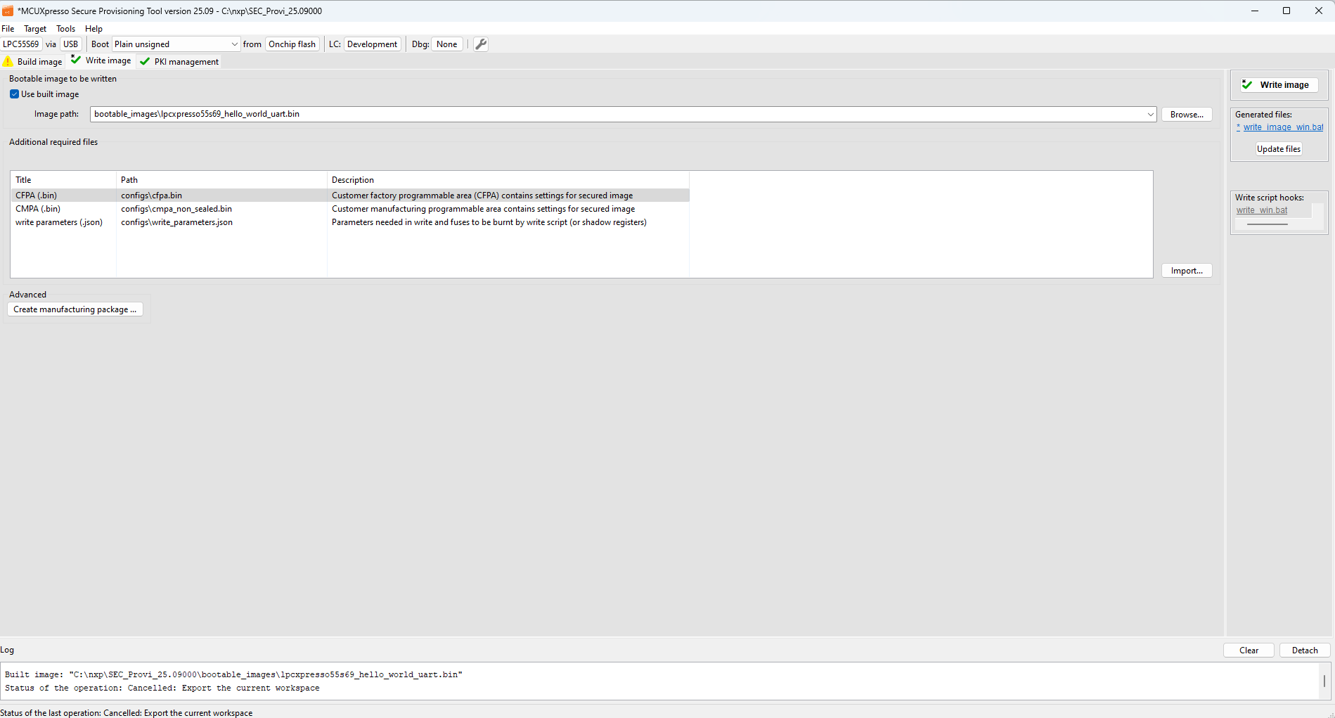
Fig. 39 Write image (LPC55Sxx)#
Controls on the write image view#
Use built image : If checked, the output of the Build image operation will be used for the write.
Bootable image : Path to the image that will be written into the target device. The file extension is specific for processor and boot type, it is either BIN for bootable images or SB for secure-binary capsules. The binary image must be in “nopadding” form without the FCB block, as the FCB block is written in a separate step.
Additional input files : Display required input files for the Write image operation. The contents depends on the processor, boot type, and other build options. By default, the contents are output files of the Build image operation. You can manually replace each file with a custom file using the Import button.
Start flashloader : Allows you to initialize and start the flashloader on the connected processor. If security is enabled in the chip, the signed flashloader is created automatically. Useful if you want to use blhost from the command line.
Test life cycle : Opens dialog that can set a temporally advanced life-cycle state. This allows it to test processor behavior in a selected life-cycle state without burning the fuses. The board must be connected by a debugger probe.
Disable flash security : Opens a dialog where the user can specify a backdoor key to disable flash security. The backdoor key can be obtained from the FCF configuration, a bootable image, or entered manually. As a final step in the flash disabling process, it is possible to execute a mass erase to clear the entire flash memory.
Write image panel : There is the Write image panel with the Write image button and the file name of the write script, on the right side of the window.
Generated files : The Generated files panel has the same functionality as Generated files on the Build image view.
Write script hooks : The panel with the hook script that is called during the write script execution. The gray label means that the file does not exist in the workspace yet. After clicking, a new file is created with the contents from the example and opened for modification. If the file exists, the label is blue and after clicking the file is opened. For details, see Script hooks workflow.
Before clicking the Write image button, ensure that the board is connected and configured to the ISP mode. If any irreversible operation is done by the write script, a confirmation dialog with details appears.
Manufacturing package#
The manufacturing package is a ZIP file that contains the write script and all other files needed for the write operation and it is designed to send the files into the factory for production. The manufacturing package can be created using the button Create manufacturing package … on the Write image page. The dialog is described in Manufacturing workflow.
In the factory, the manufacturing package can be imported using main menu > File > Import Manufacturing Package…. For more information, see Manufacturing operations.
PKI management#
The PKI management view displays the list of asymmetric keys and certificates used to validate the authenticity of the image. Generated keys can be exported for later use. PKI management allows generating the following:
keys for image authentication
key pair for debug authentication
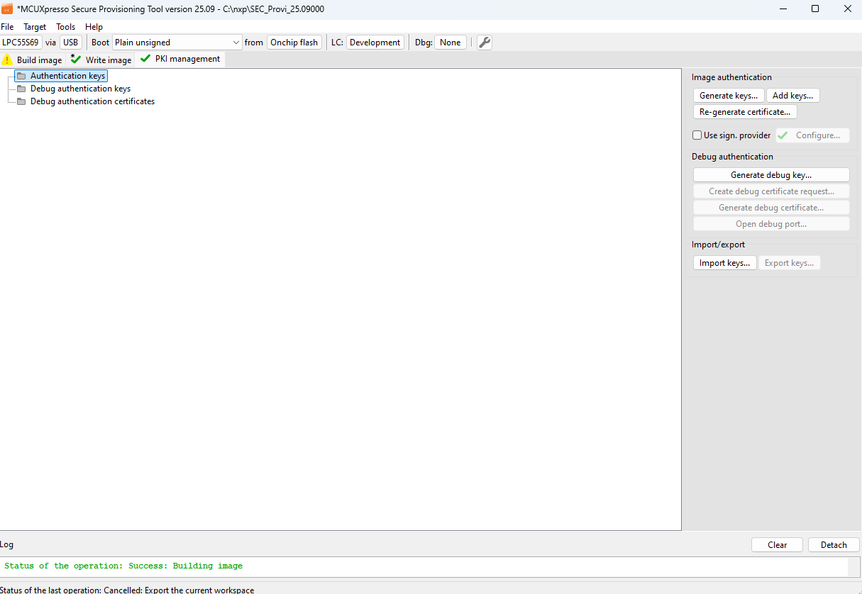
Fig. 40 PKI management (LPC55Sxx)#
Generate keys#
Authenticated images rely on a Public Key Infrastructure (PKI) set of certificates. SEC includes a graphical interface that simplifies the generation of a PKI-compatible with selected processor.
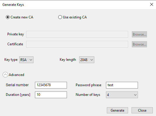
Fig. 41 Generate keys (RT1xxx)#
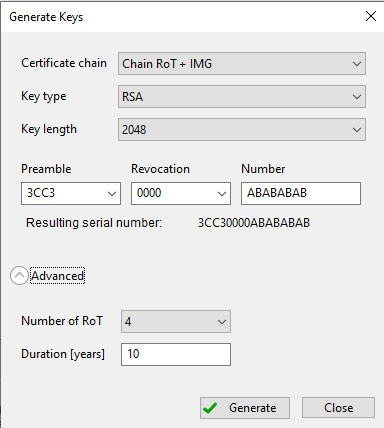
Fig. 42 Generate RSA keys#
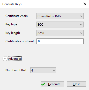
Fig. 43 Generate ECC keys#
Description of the controls in the generation dialog:
Create new CA : This option allows generating keys including a certificate
Use existing CA : Enable the use of user-specified CAs. Certificate and Private Key must be in PEM format.
Private Key : Path to the private key file
Certificate : Path to the certificate file
Key type : Generated key type. The following types are supported:
RSA: asymmetric keys using RSA cryptography
ECC: asymmetric keys using ECC cryptography
ECC+PQC: dual asymmetric keys for dual signing scheme, ECC is used as a primary signature and PQC as a secondary one.
Key length : Generated key length in bits. For the dual keys scheme, the drop-down contains all available combinations supported for the processor.
Serial number : The value is used for key revocation. The serial number for RSA keys on LPC55Sxx and RT5xx/6xx consists of three parts: preamble, revocation, and number. The revocation part is validated against the revocation field in OTP/CFPA.
Password phrase : Secure generated CA with the specified parameter. This feature is supported only for RT10xx processors.
Duration [years] : Set certificate validity to the specified duration in years. For supported devices, it is necessary for signing purposes only, as the duration is not directly verified in hardware.
Number of keys : Set to the number of keys to be generated. Most processors support up to 4 keys, with a recommended default of 4.
Certificate chain : The depth of the keychain.
Preamble : Prefix of the serial number, mandatory fixed value
Revocation : Middle part of the serial number, 16-bit revocation ID - this value should match the IMG_REVOKE field in OTP/PFR (CFPA) on the device.
Number : Suffix of the serial number bytes used to uniquely identify the certificate/key.
Certificate constraint : Used for revocation of the image signing key, validated against the revocation field in OTP/PFR. The detailed (processor-specific) information is displayed in the tooltip.
Refer to the OpenSSL documentation for additional details about the Password, Serial, and Duration options.
Once all parameters have been specified, click the Generate button. The key generation script output is displayed in the progress window.
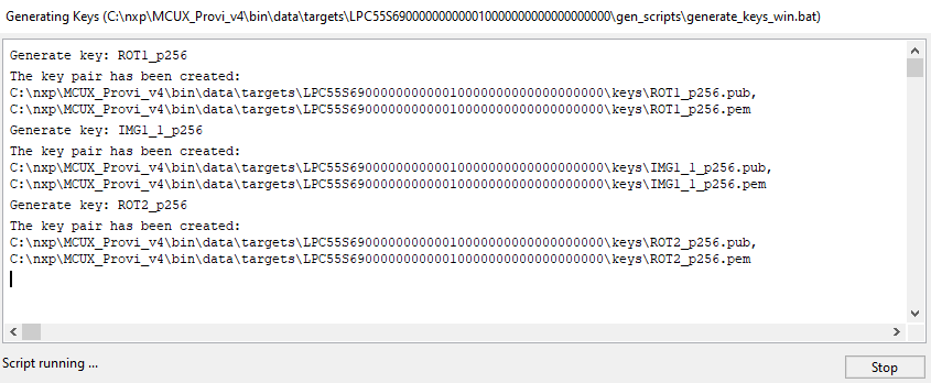
Fig. 44 Generate Keys - Progress#
Add keys#
Once keys have been generated in the Generate keys dialog, you can add additional image keys using the Add keys dialog.
IMG key path : Path of the image (ISK) key to be generated and added.
CSF key path : Path of the CSF key to be generated and added.
Key : Key type to be generated, either Image for image signing or Intermediate for creating a chain of keys
The other items are described in Generate keys.
Once you have specified your preferences, click Ok to add the keys. The output will be displayed in the progress window.
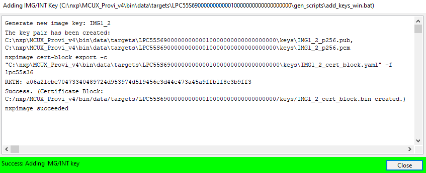
Fig. 45 Add Keys progress#
Re-generate certificate#
The SEC Tool allows re-generating a ROT or image key certificate, in case the certificate is missing or it is needed to specify different parameters (for example for certificate revocation). Select the key with the certificate and click the Re-generate certificate… button. In the dialog, review the parameters, update the serial number and confirm re-generation. The current certificate will be backed up into the backup folder and then rewritten.
The parameters for re-generation are the same as the parameters for generation; the description can be found in the previous chapters.
Import/Export keys#
You can export generated keys for later use with the help of the Export function. To export keys:
Select Export keys in the PKI management view.
In the dialog, navigate to the location you want to export the keys to, and select Select folder.
Note: Export keys also export workspace configuration, including symmetric keys, for example, SBKEK for LPC or BEE user keys for RT10xx devices.
You can later import the keys into a new workspace using the Import function. The operation makes a backup of current keys and settings inside the current workspace. The symmetric keys, for example, SBKEK for LPC55Sxx/RT5xx/RT6xx, BEE user keys for RT10xx, OTFAD keys data for RT116x/RT117x/RT118x/RT5xx/RT6xx devices, and IEE keys data for RT116x/RT117x/RT118x are restored from the imported folder.
To import keys:
Select Import keys in the PKI management view.
In the dialog, navigate to the folder containing the
keysandcrtssubdirectories with the keys info you want to import and select Select folder.
To import external keys that were not exported from the SEC Tool:
Generate new dummy keys and export them into a new folder; ensure that the number of keys matches the keys being imported.
Overwrite the keys in the exported folder with the files being imported (rename keys being imported so they match the naming convention used in the SEC Tool).
Import the keys back from the folder.
Debug authentication#
The Debug Authentication (DA) buttons are displayed in PKI management only for processors that support DA. The Generate debug key button is always enabled, Create debug certificate request and Open debug port are enabled only if the DA key exists. Generate debug certificate is enabled in a workspace with authentication keys. The Generate debug key button opens a dialog box for creating a debug authentication key pair. Generate debug certificate request allows to create a request that will be sent to the OEM, from which a debug certificate can be generated. The Generate debug certificate buttons display a certificate where the OEM selects the keys and sets the rights that will be granted to the certificate holder. The Open Debug Port dialog prepares the connected device for debugging by using the DAC.
Note: For more information, see Debug authentication workflow.
Signature provider#
Signature provider allows using a custom provider for the authentication instead of keys stored on a local machine. Signature provider requires a custom implementation of an HTTP server with a simple API providing the authentication.
Once the Use sign. provider checkbox is selected, it is possible to open the configuration dialog. When enabled, the present keys from the workspace are moved to the back-up folder. The signature provider server is used as the source of public keys and provides signing. The configuration set in the Signature Provider Configuration dialog is used in configuration files for build, key certificate regeneration, and DAC generation.
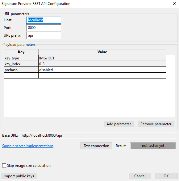
Fig. 46 Signature provider configuration#
URL parameters#
Required parameters from URL of the server:
Host host name or IP address of the server, accepted symbols as specified in RFC 3986. It is recommended to use
localhost, as the HTTP communication is not secure. For communication to another computer, it is recommended to implement a proxy server forwarding the communication via a secure channel (such as HTTPS).Port port number of the service, integer number.
URL prefix REST API prefix. Use an empty string if there is not any prefix needed.
Payload parameters#
Payload parameters are passed as a JSON payload with each request sent to the server. Each parameter is identified by a unique key and contains a text value. The following keys are reserved for the tool:
type - used by SPSDK to identify signature provider type.
host, port, url_prefix - used to specify server connection.
data - used as key for data payload of request.
key_type - used by SEC Tool to specify whether image or root key should be used; supported values are IMG or ROT.
key_index - used by the SEC Tool to identify which private key should be used. The value is a decimal number in the range 0-3 set by selecting a key from build tab ROT1 -> 0, ROT2 -> 1, IMG1_1 -> 0, IMG2_1 -> 1 and so on.
prehash - allows selecting whether to send complete data for signing or hash only. The hash algorithm can be selected from the drop-down menu; however, it is recommended to use `default`.
key_algorithm - allows selection of the keys to be imported; this option is enabled only on processors that support multiple key algorithms.
Signature provider server API#
Signature provider API must implement the following three endpoints, and optionally one additional endpoint:
sign
sign handles signing of the given data block; the request sends the data to be signed with a private key specified by optional parameters. Example of the signature request for MCX947 with ROT1 or ROT1-IMG1_1 selected as signing key: ‘http://localhost:8000/server/sign’ json payload:
Certificate signing with ROT1 key:
{
   ″data″: ″hex string of certificate block to be signed″,
   ″key_type″: ″ROT″
   ″key_index″: 0
   ″prehashed″: ″none″ if not prehashed, hash algorithm name if data are prehashed
}
Image signing with IMG1_1 key:
{
   ″data″: ″ hex string of image block to be signed″,
   ″key_type″: ″IMG″
   ″key_index″: 0
   ″prehashed″: ″none″ if not prehashed, hash algorithm name if data are prehashed
}
signature_length
signature_length returns the signature length in bytes.
verify_public_key
verify_public_key verifies that the used public key forms a valid key pair with the private key that is on the server. The public key is sent as a data payload, the RSA key is sent in NXP proprietary format and the ECC key is sent in DER format. To identify the private key that should be matched with this key, use optional parameters. In the case of matching keys, return “true”.
This API is designed to detect a problem if the server is using a key different from the client one. For environments where such validation is not needed, the implementation can return simply “true”.
public_keys_certs
public_keys_certs is an optional endpoint. If implemented, it allows importing public keys from the Signature provider dialog into the SEC Tool. The SEC Tool expects the response from this endpoint to be a tree of Authentication keys, ROT keys at the top level, and IMG keys as the leaves. The structure of the response is described in <install_folder>/bin/_internal/schema/signature_provider_key_tree_schema_##_##.json. In general, any tree that can be generated from the Generate keys dialog can be imported, with the limitation of one child key for the root key. RSA trees do not need to have the same key length for each subkey. For key trees that include a CA, the certificates are represented as hexadecimal values and follow the structure CA->SRK->CSF&IMG.
Server examples#
Server examples are part of the SEC Tool distribution. There are Python script examples with the server implementation. These examples are described in Signature provider workflow.
Manufacturing Tool#
Use Manufacturing Tool to provision several devices connected to the host at the same time. Manufacturing Tool can be accessed from Tools in the menu bar. The devices can be connected to the host using USB or UART or SPI or I2C. The user interface is made of these areas: Operation, Command, Connected devices, Communication parameters, and the button bar. If trust provisioning is supported for the processor, there is also a Trust provisioning area.
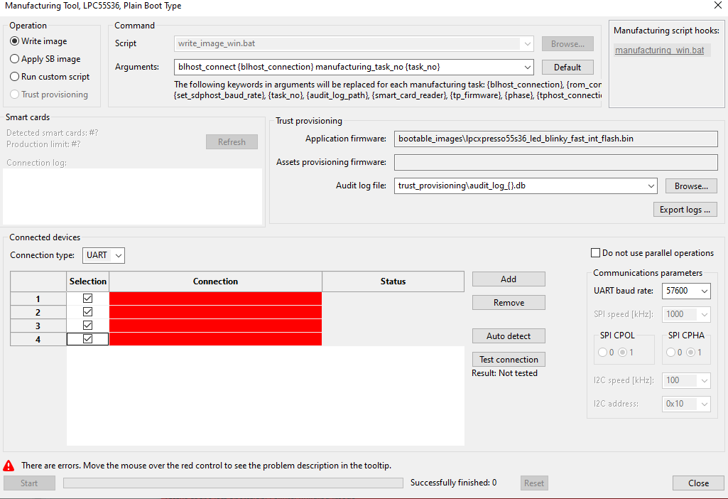
Fig. 47 Manufacturing Tool#
Operation : The Operation area contains radio buttons representing different operations to choose from.
Write image : Performs the same operation as Write image. Before use, the image must be built in the Build image view, and the Write image view must not show any errors.
Apply SB image : Uses an SB (Secure Binary) capsule to update the existing image of the processor. For most of the processors, the SB file is created during the build secure image operation and is located in the bootable_images subfolder of the workspace by default. For RT10xx/RT116x/RT117x/RT118x processors, the SB file must be created manually, as it is currently not supported by SEC Tool.
Run custom script : Uses a custom script to configure provisioning. It is assumed that the script is a modified SEC write script accepting SEC parameters (especially connection parameters). Exit status 0 is considered a success.
Command : The Command area contains parameters needed for the operation selected in the Operation area. The parameters vary based on the selected operation.
Script (Write image, Run custom script) : Path to the write or custom script. To locate the custom script, use the Browse button.
SB file (Apply SB image) : Path to the SB capsule. To locate the file, use the Browse button.
Arguments : List of arguments used during the operation. Use the Default button to revert any changes. The keywords enclosed in curly braces in arguments will be replaced for each manufacturing task. You can find the complete list of keywords with descriptions in the tooltip.
Manufacturing script hooks : The panel with the hook script that is called at the start and end of the manufacturing script execution. The gray label means that the file does not exist in the workspace yet. After clicking, a new file is created with the contents from the example and opened for modification. If the file exists, the label is blue and after clicking the file is opened. For details, see Script hooks workflow.
Trust provisioning : Configuration of the trust provisioning operation.
Application/Assets provisioning firmwares : These file paths are listed for information only.
EdgeLock 2GO API key : Access key for EdgeLock 2GO server. It can be specified here or in environment variable
SEC_EL2GO_API_KEY.EdgeLock 2GO server: Test connection : Allows testing the connection with the EdgeLock 2GO server.
EdgeLock 2GO product batch DB : Path to EdgeLock 2GO secure objects database used for the per product (offline) flow.
Connection type : Allows selecting a communication interface with the processors.
#phases
: A number of phases being executed for one device. The USB device identification passed to write the script might change after reset (see USB path). If the write image script supports the USB connection, the script is executed in phases, which basically means the script is invoked several times with different manufacturing_phase argument. Each phase is finished by reset and the USB identification is updated before executing the next phase. This parameter allows overriding the number of phases being executed and a forced custom number. Value disabled means that the phases are not used. It is recommended to use the default value. If the default value is selected, the current number of phases is displayed in the tooltip. The custom value shall be used only if the write script was modified manually.
Do not use parallel operations : the check box allows disabling parallel operations in the manufacturing. This can be used if any problem with parallel operation is detected.
If the parallel operations are enabled, the execution order is the following:
flashloader is started for all connected devices in parallel, if flashloader is needed
USB path is updated for all devices (if USB connection type is used)
phase 1 is executed for all connected devices in parallel (+soft reset)
USB path is updated for all devices (if USB connection type is used)
flashloader is started for all connected devices in parallel, if flashloader is needed and USB path is updated for all devices (if USB connection type is used)
phase 2 is executed for all connected devices in parallel (+soft reset)
Connected devices : The connected devices area contains an interactive table displaying all connected devices. The tool can detect and program devices connected using USB only if they are in ISP mode.
Columns:
Selection : allows users to enable/device; each device is configured in the table. If the device is de-selected, the next autodetection keeps the device de-selected.
Connection : allows users to enter manually the device name or path.
Status : Displays the status of the connected device. After the operation was executed, the log file can be opened by clicking the entry in the Status column
Buttons to modify Connected devices:
Select all : A button to select all devices in the table below.
Deselect all : A button to deselect all devices in the table below.
Autodetect : A button to detect automatically all devices connected to the host for a selected connection type. It is the recommended usage. For more information about the USB path, see USB path.
Add : A button to manually add a device (add an empty row to the table).
Remove : A button to remove the selected device from the table (remove the selected row).
Test connection : A button to test (ping) the selected devices. This feature might be useful for UART, SPI, and I2C devices where the detection of the communication device (COM port or USB path) does not imply that the connection with the processor is established. Therefore, a test connection is recommended before starting the manufacturing operation.
Export logs : Allows exporting manufacturing logs as a ZIP file. Besides exporting all logs, it is possible to export logs for a specific day only.
Load KeyStore (Apply SB image for RT5xx/6xx) : Load KeyStore from external flash before uploading the SB file.
Communication parameters : Configuration of the connection with the device. The Baud rate option allows selecting a value from the drop-down list or specifying it manually. The detailed description of the parameters can be found in the Connection chapter.
Crystal freq. [kHz]
: Frequency of the external crystal used as a clock source for the processor. This is used only for lpcprog tool.
Button bar : The Button bar contains action buttons and displays any warnings and alerts.
Start : Starts the selected and configured operation. You can observe the progress of the operation in the adjacent progress bar.
Successfully finished : Label with the number of successfully finished operations. This number is incremented automatically and stored in the settings file in the workspace.
Reset : The button allows resetting the “Successfully finished” counter.
Close : Closes the Manufacturing Tool without running the operation.
USB path#
The Manufacturing Tool supports the use of Serial, USB, SPI, or I2C connection. In most cases, the Auto-detect function is sufficient for detecting the connected devices. The USB path is used to identify the USB device for USB, SPI, or I2C communication, so the devices with the same USB VID and PID can be identified uniquely. It differs depending on the operating system. The description of the USB path format can be found in the SPSDK documentation.
The Manufacturing Tool supports automatic USB path update that may happen during the manufacturing operation because of the following reasons:
On some operating systems, the USB path changes after each device reset.
i.MX RT1xxx processors in ISP mode have different VID and PID compared to the VID and PID of the flashloader application (which cannot be booted at the start of the manufacturing phase).
After the update, the Manufacturing Tool automatically executes the second part of the script that finishes the required operation.
Note: i.MX RT10xx and RT11xx devices in ISP mode have different VID and PID compared to the VID and PID of the flashloader application, which is uploaded to the target to program the flash. Auto-detect searches for devices with PID and VID when the target is reset in the ISP mode. If the flashloader is active on the device, reset it into ROM bootloader mode, otherwise the device will not be detected. The manufacturing process is slightly different then write script: as a first step, the flashloader is uploaded to all boards and its USB path is retrieved. After this step, the rest of the process is executed in parallel.
Flash Programmer#
Flash Programmer is designed to read/write from the currently selected flash memory and supports all flash types including internal flash, external NOR and NAND flash, SD card, and eMMC. Flash Programmer can be accessed from Tools in the menu bar. The processor can be connected to the host using USB, UART, SPI, or I2C and must be in ISP mode (as the tool internally uses the blhost or lpcprog protocol), or a via debug probe. Flash Programmer can also be used to prepare data for writing, or just to display or modify saved memory blocks even if no device is connected. The left side contains the action toolbar and the right side contains a buffer of the memory content in hexadecimal and ASCII formats. The tool has additional functionalities: “Auto erase” and “Auto verify”. To display memory value from some address, fill in the start address into the Address combo and required size (in Bytes) into the Size combo. Click Read and the value read from memory will be displayed. The result of the operation is displayed in the bottom-left corner. If the operation ends with failure, more detailed information about the encountered error is displayed in the tooltip. The settings of the Flash Programmer window are not saved into the workspace. They are discarded if the tool is closed.
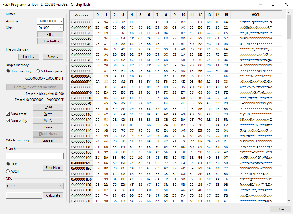
Fig. 48 Flash Programmer Tool#
Buffer : The buffer represents a part (copy) of the flash memory that will be written or read from the processor. The buffer is defined by the address, size, and content.
Address : Specifies the start address of the buffered space. The address cannot go lower or above the start or end address of the target memory.
Size : The size of the buffer specifies how many bytes should be read or written or erased. The size is limited to 16 MB.
Fill … : Opens a dialog that can fill the buffer with value (byte, word, double word, or random). Word and double word can be applied as big or little endian.
Clear buffer : Clears displayed values and set the size to 0.
File on the disk : Load/save operations with a file on the disk.
Load … : Loads the file into the buffer;
.srecand .hexfiles are loaded with formatting (start address), other file types are processed as binary files without start address information. The address is the start address in the buffer where the value should be loaded, size tells what portion of data from the start should be loaded. The loaded data are merged with the existing buffer context (for example, the buffer can be extended) and the overlapping areas are overwritten. Load is also supported via drag-and-drop functionality, allowing files to be added directly to the gridSave … : Saves buffer or portion of buffer into a file. The supported file formats are
.srec, .hex, and.bin.
Connection type : The type of connection used to communicate with the target processor.
ISP Mode (default) : The processor can be connected to the host using USB, UART, SPI, or I2C and must be in ISP mode.
Debug Probe : The processor can be accessed through a debug probe, with the following limitations:
Only read operations are supported.
The processor should not be in ISP mode, as the debug probe usually cannot access the memory in this mode.
It is possible to access only the memory in the address space, not bootable memory.
Target memory : This block provides basic operations on target memory. The hex range on the top is the working memory range of the selected memory.
Selection of the memory type : Select which memory should be targeted:
Boot memoryrefers to the same memory as selected in the tool panel.Address spacerefers to the entire address space of the processor. TheBoot memorycan be re-configured directly from the tool using button below, while for theAddress spacethe tool expects the memory is already available.Configure : Tries to configure the connected external memory. It executes the same memory configuration as in the Boot memory configuration. If it is SPI-NOR memory with FCB, then the last step of configuration tries to read the size of the minimal erasable block.
Erasable block size : Defines the minimal erasable block size. This value is read from FCB if available or from the boot memory configuration for memories that do not use FCB. If no erasable block size is found, it is not possible to compute the erased size.
Erased : The address range, which will be erased by the erase operation. The address range is determined by the buffer address and size, and it is aligned to an erasable block boundary. If the buffer is not aligned with the erasable block size, a warning is displayed.
Read : Reads memory of a given range to fill the buffer. For memory types with ECC, reading is not possible if the memory is erased.
Write : Writes values in the buffer to the memory, see also the options “Auto erase” and “Auto verify”
Verify : Checks whether the values in the buffer match values in memory, values that do not match are highlighted with red color and the tooltip displays the value that is in the memory
Erase : Erases the memory, always erases the closest upper multiplication of minimal erasable block size.
Blank check : Checks if the memory is blank or not supported for internal flash.
Erase all : Erases entire memory.
Auto erase : On the write operation, the memory is erased before writing.
Auto verify : After the write operation, verifies that that buffer was written properly.
Search : Search for a value in the buffer; the value can be provided as HEX numbers grouped as bytes (“FF AA”, “12 A3 00”) or ASCII (“abc”, “hello world”). The found value is highlighted in blue and the start address is displayed in the left corner.
CRC : Compute CRC of the selected type for the buffered data.
SB editor#
The SB Editor Tool is designed to create custom secure binary files for updates of the SW, data, and/or processor configuration. The SB editor supports SB formats: SB2.x, SB3.x, SB4.x, and SBx and also supports both regular SB file and device HSM SB file. The SB editor can be started using the command main menu > Tools > SB Editor. When the SB editor is opened for the first time, and the workspace already contains a YAML file with the SB configuration (which is recommended), the SB Editor Tool offers to import the file.
SB files are generated using the nxpimage or nxpdevhsm command-line utilities, so the SB editor produces a configuration YAML file that is used as input for those tools. The SB editor is a smart GUI editor for the YAML configuration file. In the GUI, there are also supported “$” extensions (see high-level commands and $ variables), that are translated into the corresponding values in YAML.
SB editor contains the following main UI parts:#
Top buttons bar : The bar that allows selecting the SB file type, import, export, or clear the current configuration.
Properties : The view that allows specifying properties for SB file generation.
Commands : The view that allows specifying the sequence of commands that shall be executed in the SB file.
Output : The panel, where the output files (the configuration YAML file and the resulting SB file) can be specified. The button View allows users to update the YAML configuration file and open it in an external editor. The button Generate allows to (re-)generate the resulting SB file.
Command for the SB file generation : The label with the command for generation of the SB file from the configuration file.
Status and bottom buttons : The buttons that allow creating a manufacturing package and starting manufacturing tool, see SB file in manufacturing. The OK/Cancel buttons allow closing the SB editor with or without saving the configuration into the workspace.
File type#
The SB editor supports the creation of:
Secure Binary - a regular SB file that is secured by OEM keys specified on the Build view. Internally, there are supported several SB file formats (SB2.1, SB3.1, and so on - this depends on target processor), but they are all unified under the same configuration GUI in SEC Tool. The properties and commands for each format might be different.
Device HSM SB file used for device HSM secured by device-specific keys. Creation of this SB file requires the processor to be connected to the computer. For details, see Connection.
The properties and commands for each file type might be different, so switch the file type may affect the current configuration.
It is recommended to avoid modification of the device HSM SB file because modifying the default sequence of commands may cause a risk of exposing OEM assets during factory provisioning. The SB file is sent to the processor in blocks, and command atomicity across blocks is not guaranteed - external link manipulation may interrupt execution. Command order matters - an incorrect sequence could leak sensitive assets if the device falls back to ISP mode. Proceed only if you fully understand the security implications.
Properties view#
The properties view allows editing general properties and property lists. In case the processor contains any list-type property, it is selectable on the left side and the right side displays a property editor table. If no list-property is supported for the processor, the GUI displays just a property editor table.
The property editor table contains the following columns:
Group : The properties are logically grouped (for information only).
Property : Name of the property (for information only)
Value : The value of the property. If the value is not specified, there is an empty string. The value can be of the following type: integer number; string; predefined options (drop-down list), which include logical type (#true/#false); file path
Resolved value : In case the value is specified in the form of ${variable}, this column contains the value of the variable; otherwise, it is the same as the value.
The property description is displayed in a tooltip.
Commands view#
The view allows specifying the sequence of the commands that will be stored in the SB file and will be executed in the target processor. There are two types of commands: high-level and low-level. High-level command sequences are sequences of low-level commands that are typically used in SB files and are designed as SEC-tool specific extension of the low-level commands. These commands simplify creation/modifications of the SB file and will be replaced by low-level commands during the generation of the configuration YAML file. The names of all high-level commands start with $. High-level commands do not have any arguments, and the parameters of the commands inside cannot be modified. However, it is always possible to replace a high-level command by a set of the corresponding low-level commands and then customize the low-level commands. High-level commands may contain an optional low-level command that is stored into YAML only if all variables for the low-level command are defined. This is used if a high-level command might be extended in some configurations. Use a high-level command instead of a low-level command, as high-level commands are updated with the SEC Tool configuration.
The commands page contains the following panels:
The command sequence : The list of commands to be generated into the SB file. It is possible to select whether there will be displayed $ variables or real values.
Button |
Description |
|---|---|
|
Add - to add the selected command into the current sequence |
|
Delete - to remove the selected command from the current sequence |
|
Move - to move the selected command up or down in the current sequence |
|
Expand - to expand a high-level command sequence into the list of low-level commands |


All available commands : The tree with all available commands is divided into “High-level command sequences” and “Low-level commands”.
Variables : Table of $ variables applicable as command arguments. It is possible to select whether the table should contain all variables or command-specific variables (the property-specific variables are not displayed).
Selected command : This panel shows the parameters of the selected command in a table.
Command parameters
: The parameters for the selected command can be specified in the table at the bottom of the commands page. The first column represents the command itself and the other columns represent the command parameters. If the parameter is required, not specifying it results in an error. The description of the parameter is displayed as a tooltip. Use ${variable} for parameter values, because these variables are updated within the SEC Tool configuration.
For a high-level command, an informative description is displayed instead of a parameter.
$ Variables#
To allow reuse of a SEC Tool configuration for the SB file generation, $ variables are provided. Names of these variables consist of the $ character and the name is enclosed in curly braces (for example, ${family}). The variables are used for properties and command parameters. For properties, the $ variable name matches the name of the property. The list of all variables can be found on the Commands page at the right. It is possible to filter the variables to hide variables for “properties” or display all variables. The variables are not editable; however, it is possible to copy the name or value into the clipboard.
Validation#
All the input values are validated and any problems are displayed in the window. Before generating the SB file, the YAML file is validated using the JSON schema. If any validation fails, the SB file cannot be generated.
It is recommended to create a SEC Tool workspace with the SB file, import the working configuration into the SB editor and start updating the working configuration.
SB file in manufacturing#
Creating a manufacturing package button : If the SB file is applied on another computer (or in a factory), it is possible to create a manufacturing package that contains all the needed files. The package can be imported on another computer, see Manufacturing workflow.
To Manufacturing button : The button allows opening the Manufacturing Tool and applying the created SB file into a processor without creating a manufacturing package.
Merge Tool#
The Merge Tool allows users to merge up to 8 images, given by the user, into one single binary image.
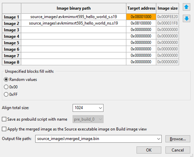
Fig. 49 Merge images tool#
The configuration allows users to specify:
Images : Table to specify the path and target address for each image that used to be merged
Fill pattern : Pattern used to fill empty gaps between images, such as random value, 0x00, or 0xFF
Align total size : Align the size of the entire merged image
Pre-build script option : Merge script is executed when the OK button is pressed, but it can be stored as given pre-build script to be executed before build script.
Apply the merged image as the source executable image : Allows applying the merged image as a source executable image on the Build image view when the merge script is done
Output file path : Path where the merged binary image is stored on a disk