
Encrypted XIP using IPED#
This document extends the documentation of MCUboot and encrypted XIP in OTA examples and provides additional information related to the IPED module.
Note: The extension currently supports only the IPED module based on the GCM algorithm in RW61x devices.
1. Introduction#
IPED (Inline PRINCE Encryption/Decryption for off-chip flash) is an encryption unit for external flash, specific to the NXP RW61x, RT700 and MCX N MCUs.
The IPED engine generates an 8-byte authentication tag for each 32-byte block of encrypted data. When storing this encrypted data in Flash memory, the FlexSPI controller organizes it in a specific pattern:
Each block of 32 bytes of ciphertext is followed by 8 bytes of authentication tag data (total: 40 bytes per unit)
The authentication tags are stored physically in flash but are hidden from the CPU’s logical address space (AHB read, fetch) - the CPU only sees the decrypted payload
Due to this interleaving scheme, the actual physical flash consumption is 1.25× (5/4) the logical address space visible to the CPU
Following image shows an example of a valid IPED region configuration for MCUboot slot - logical to physical address mapping

There are several points to be aware of when using IPED in an OTA process:
Resulting consumption of physical memory
range of IPED region is defined in terms of logical address but the physical memory consumption is 1.25× the logical memory consumption
OTA process must ensure the installed OTA image doesn’t overlap the maximal size of the IPED region. The NXP MCUboot hooks enforce this: if the output (encrypted) image would exceed the primary slot (including the slot trailer), the image is rejected and invalidated. Rather than relying on runtime rejection, it is strongly advised to constrain the application up front — adjust the output binary size in the linker file and/or check the image size before encryption — so the app fits within the slot budget (roughly
slot_size / 1.25, minus the trailer)
Flash operations have to respect the boundaries of the flash page/sector size and the encryption unit size
due to internal software arbitration, only the ROM IAP can be used for flash writes
the size of a data chunk must be aligned to 4 * page size; no partial writes are allowed - the last data chunk must be padded with dummy bytes
IPED region usage and collisions
the MCUboot IPED initialization (NXP customization) implicitly uses IPED region 14 and 15; region 0 is reserved for MCUboot. IPED has 15 regions total, of which the first 4 can be initialized by ROM at startup and the rest only manually
Reading raw flash of slot 0 with a debugger returns ciphertext
this is expected. The ROM initializes its IPED regions during debugger startup, so those regions return decrypted data. The IPED region covering slot 0 is set up manually by the bootloader at runtime, so it is not initialized in the debugger context and you correctly observe ciphertext there
The whole IPED initialization, metadata handling and image re-encryption are implemented in encrypted_xip_platform_iped.c, bootutil_hooks.c, and the flash backend porting layer.
Additional information about IPED in RW61x can be found in its reference manual.
2. Troubleshooting: unexpected resets / reset loops (IPED / PRINCE)#
If you observe an unexpected reset or a reset loop, inspect the ITRC status register to determine which IP module triggered the reset. Of particular interest is the IN12_STATUS bit (PRINCE IP module detected an error event).
When IN12_STATUS is set, the most common cause is that code tried to execute or fetch from an IPED region containing invalid ciphertext. The IPED/PRINCE module treats this as a security violation and forces a reset. For example, a pointer that reads an erased flash area inside an IPED region has no valid data to decrypt, the IP module faults, and the device resets.
ITRC status register read example:
PRINTF("At(0x%x) is 0x%x \n\r", (0x40024000), *(volatile uint32_t *)(0x40024000));
Debugging an issue in a reset loop is tricky because the fault happens before you can attach. A practical technique:
Near the very start of the application add a spin loop so the program halts there:
volatile int test = 1;
while (test);
Attach a debugger to the running target. This is necessary because the customized MCUboot initializes the IPED region at runtime (the ROM does not do it during startup), so the IPED configuration only exists once MCUboot has run and handed off to the application.
From the debugger, set
test = 0and single-step through the code to find the exact line that triggers the reset (most likely an access into an IPED region with no valid ciphertext).
3. Metadata structure#
The structure follows the ROM code, but the IPED configuration is handled manually from the MCUboot context.
Metadata Flash Sector (IPED)
━━━━━━━━━━━━━━━━━━━━━━━━━━━━━━━━━━━━━━━━━━━━━━━━━━━━━━━━━━━━━━━━━━━━━━━━━━━━━━

 0                    ┌─────────────────────────────────────────────────────┐
                      │  tag           [4 bytes]                            │
                      │  params        [252 bytes]                          │
                      │    configId    [4 bytes]                            │
                      │    princeRnds  [4 bytes]                            │
                      │    regionOff   [4 bytes]                            │
                      │    ipedConfig  [60 bytes]  × 4 = 240 bytes          │
                      │      start     [4 bytes]                            │
                      │      end       [4 bytes]                            │
                      │      flags     [1 byte]                             │
                      │      padding   [3 bytes]                            │
                      │      encIv     [48 bytes]                           │
                      │        iv      [16 bytes]                           │
                      │        cipher  [16 bytes]                           │
                      │        tag     [16 bytes]                           │
 +256                 ├╌╌╌╌╌╌╌╌╌╌╌╌╌╌╌╌╌╌╌╌╌╌╌╌╌╌╌╌╌╌╌╌╌╌╌╌╌╌╌╌╌╌╌╌╌╌╌╌╌╌╌╌╌┤
                      │                                                     │
                      │              (erased 0xFF)                          │
                      │                                                     │
 SECTOR_SIZE/2        ╠═════════════════════════════════════════════════════╣
                      │                                                     │
                      │              (erased 0xFF)                          │
                      │                                                     │
 SECTOR_SIZE-32       ├─────────────────────────────────────────────────────┤
                      │  enc_confirm_t [32 bytes]                           │
 SECTOR_SIZE          └─────────────────────────────────────────────────────┘
━━━━━━━━━━━━━━━━━━━━━━━━━━━━━━━━━━━━━━━━━━━━━━━━━━━━━━━━━━━━━━━━━━━━━━━━━━━━━━
flexspi_nor_mem_image_iped_config_t (256 bytes, 16-byte aligned):
  [  0..  3]  tag                        (4 bytes)   "IPCB" (0x42435049) validity marker
  [  4..  7]    configId                 (4 bytes)   engine selector: kNBOOT_MemCryptIped (0x95959595)
  [  8.. 11]    ipedPrinceRounds         (4 bytes)   number of PRINCE rounds: 12 or 22
  [ 12.. 15]    regionOffset             (4 bytes)   lowest IPED context register index
  [ 16..255]    ipedConfig[4]          (240 bytes)   4 × nboot_iped_region_config_t (60 bytes each):
  [ +0.. +3]      startAddress           (4 bytes)   IPEDx_START register value
  [ +4.. +7]      endAddress             (4 bytes)   IPEDx_END register value
  [ +8.. +8]      regionFlags            (1 byte)    bit0=enabled, bit1=locked
  [ +9..+11]      padding                (3 bytes)   explicit alignment padding
  [+12..+59]      encryptedIv           (48 bytes)   AES-GCM protected IV blob:
  [+12..+27]        iv                  (16 bytes)   AES-GCM nonce used to encrypt the IV
  [+28..+43]        ciphertext          (16 bytes)   encrypted IPED region IV
  [+44..+59]        tag                 (16 bytes)   AES-GCM authentication tag

enc_confirm_t (32 bytes):
  [  0.. 31]  magic                  (32 bytes)   written last in a separate flash page — confirms config block
                                                  was fully persisted; absence signals incomplete OTA update
4. Encryption of MCUboot (OVERWRITE_ONLY only)#
Encrypting the MCUboot partition is required only when a private key used for offline encryption is embedded in the bootloader code as a C array; otherwise it is optional.
To simplify the workflow, the MCUXpresso Secure Provisioning Tool (SEC tool) is used.
To provision the device and encrypt the bootloader perform the following steps:
Erase the device
Build
mcuboot_opensourceGet the device into ISP mode
On development boards this is typically done by holding the ISP button and pressing the reset button
Open the SEC tool and create a new workspace for the RW61x target device
Test the ISP connection in the SEC tool
Switch to PKI management tab
Click Generate keys (leave default settings)
Build Image
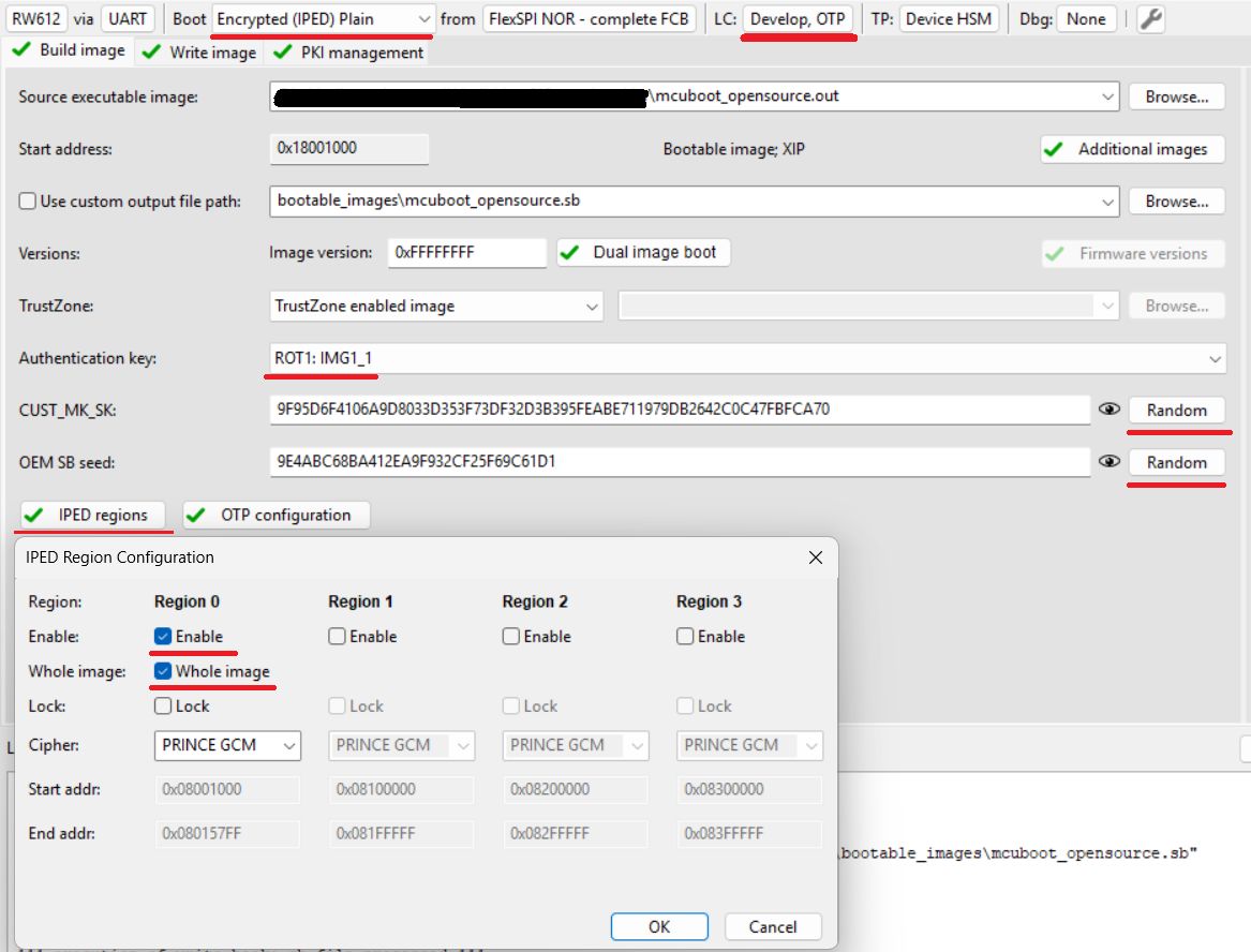
Boot: Encrypted (IPED) Plain
Select the
mcuboot_opensourceoutput binary or ELF image as Source executable imageLifecycle: Develop, OTP
Select an authentication key and generate CUST_MK_SK and OEM SB seed
Click Build image
Configure IPED regions
Click IPED regions
Configure Region 0 for the MCUboot partition as shown in the following image (Region 1 is reserved for the execution slot)
Write image
Click Write image
Note: This operation provisions the device with RKTH and CUST_MK_SK permanently, but the board remains usable for development purposes, as OTP BOOT_CFG0 (fuseword 15) remains intact. A user is advised to save the SEC tool workspace (or at least the keys) for future use.
5. Initial SB3 image, OTA SB3 image (FLASH_REMAP only)#
Note: Encrypted XIP with FLASH_REMAP support is currently in an experimental state. The mode can be evaluated only with ota_mcuboot_basic example
Due to the customized placement of the configuration structures outside the FCB, an initial SB3 is required for safe deployment during end-product manufacturing. The SB3 container can also be used as a secure capsule for a signed image, providing encryption during the OTA image transport. Additional information can be found in the SB3 documentation.
Note: The device must be provisioned with RKTH and CUST_MK_SK. For provisioning, you can follow the previous chapter.
To simplify the workflow, the MCUXpresso Secure Provisioning Tool (SEC tool) is used.
Build
ota_mcuboot_basicand sign the image withimgtoolas usual.Look into the
ota_examples/_common/sb3_templatesandota_examples/_common/binariesdirectories and copy the template and additional binaries to your$sec_tool_workspacerw61x_IPED_initial_image.yamlfor the initial imagerw61x_IPED_ota_slot0_image.yamlorrw61x_IPED_ota_slot1_image.yamlfor OTA imageiped_conf_magic_page.binmagic (confirmation) for configuration structureslot_trailer_page.binMCUboot slot trailer with confirmation flag (required for DIRECT-XIP mode)
Extract the FCB from the
mcuboot_opensourcebinary and place it in thesource_imagesfoldernxpimage utils binary-image extract -b mcuboot_opensource.bin -a 0x400 -s 512 -o parsed_fcb.bin
In the SEC tool, open Tools/SB Editor and click Import to import the template
Check and, if necessary, fix the paths to the keys and the image binary
Click Generate
alternatively use SPSDK directly:
nxpimage sb31 export -c template.yaml
For initial image:
Get the device into ISP mode
On development boards this is typically done by holding the ISP button and pressing the reset button
Test the ISP connection in the SEC tool
The initial image can be loaded using
blhostblhost -t 100000 -p COM3,115200 receive-sb-file initial_image_slot_0.sb
For an OTA update using SB3, follow the instructions in MCUboot and encrypted XIP in OTA examples.