Generic workflows
This section provides information on workflow for some typical use cases. These chapters are not specific for any processor.
Smart card trust provisioning workflow
This workflow describes trust provisioning using a smart card. It can be used for processors that support this feature.
Trust provisioning allows OEMs (Original Equipment Manufacturers) to contract manufacturing of the product by a third-party company including firmware provisioning without access of the third-party company to the OEM confidential assets (such as application firmware and keys).

High-level trust provisioning workflow
High-level workflow description:
OEM develops application firmware (sb file capsule). OEM generates keys and configures the smart card with the keys and other assets. OEM creates a manufacturing package with the application firmware.
OEM sends the smart card and manufacturing package to the factory.
In the factory, the firmware is provisioned into flash, the record is added into the audit log for each device.
The factory sends the audit log to OEM.
OEM checks the validity of the audit log and the number of devices being manufactured, optionally extracts certificates, and uploads them to the cloud.
Features:
Application firmware is encrypted using OEM keys.
Smart card is used to secure the OEM keys.
Smart card contains the production counter, so OEM can control the number of products.
Simple manufacturing dialog allows producing of several devices in parallel.
Audit log in SQL-lite DB format.
Optionally, there can be generated up to 4 device identity certificates for each product.
For details, see a demo video (webinar) at NXP website
Preparation of OEM-specific inputs
To start trust provisioning, you need:
Smart card - Please contact NXP local representatives for smart cards. Starting from SEC tool version 7, a smart card with applet version 1.2 or above is required.
Processor that is supported for trust provisioning.
Application firmware - bootable application built with a secure boot type (authenticated or encrypted). The application must be built in the Build image view. SBKEK must be specified.
The secured life cycle is configured in the toolbar.
Note: For development purposes, it is possible to use the development life cycle, but only on the LPC55S36 processor
Valid PFR Configuration in the Build image view. The CFPA version must be higher than the CFPA version in the current processor (it is recommended to add at least 10), otherwise the CFPA page cannot be updated.
The audit log key and optionally also the certificate signing key. These keys can be provided externally or created on the PKI management view (See PKI management ).
For the LPC55S3x device, an HSM provisioning SB3 file that contains CFPA and CMPA; the format of the file is different for a smart card, so it must be re-built after the card is selected.
Asset provisioning firmware.
The firmware is distributed within the SEC tool; however, for some processors, part of the firmware is delivered as restricted data. For details, see Preferences.
Optionally, you can also configure the device identity for IoT (Internet of Thing) devices. This feature is described in Device identity and cloud service provider registration.
Configuration of smart card at OEM
After you have all inputs, enable the smart card trust provisioning type on the toolbar. Click the Detect button to find the smart card. Click the Test connection button to ensure that the smart card is recognized by the tool and communication can be established.
After you enable the smart card, the Smart card management view is enabled. You can generate trust provisioning keys (certificate signing key and production audit log key) in the PKI management view. Review and configure all items at the smart card configuration (For more information, see Smart card management. Then hit the Prepare smart card button.
Note: You cannot generate the certificate signing key and audit log keys until you enable the smart card.
For development purposes, you do not need to seal the smart card immediately. The unsealed smart card can be reconfigured. It is recommended to test the smart card before it is sealed.
SBKEK and PFR Configuration are also stored on the smart card, reconfigure the smart card if there are changes in any of them.
Testing the OEM configuration
This describes how to verify trust provisioning on the OEM side. This step is optional; however, it is a good practice to ensure trust provisioning works with your configuration.
Use a new empty processor.
If you have previously used the processor, ensure that no fuses are burnt and the processor is still in the development life cycle. Use the Clear CMPA button in the PFR configuration dialog to clear the CMPA page. Ensure the CFPA version being provisioned has a higher version than the CFPA page currently used in the processor. Erase the whole flash.
Open the manufacturing dialog from the Main menu > Tools > Manufacturing Tool and confirm to re-generate the trust provisioning script. Select the trust provisioning operation, use default arguments for the trust provisioning command.
Ensure that the smart card is properly selected and click the Refresh button to check that communication with the smart card can be established and the production limit on the card is non-zero. Ensure the application firmware and provisioning firmware and audit log are selected. For some processors, there might be two different versions of provisioning firmware depending on the silicon revision. In this case, provisioning firmware is not selected by default, it is auto-detected by the Test connection button.
Boot the processor into the ISP mode and connect it via a serial port or USB to your computer.
Click the Auto detect button to update the connected board in the Connected devices table.
If the corresponding serial port is listed, ensure it is enabled and all other serial ports are disabled and click the Test connection button to ensure that the communication with the target processor can be established. Verify, that all connected devices are listed in the table. If the table contains devices, that should not be configured, such as other serial ports with other devices, disable them. Then click the Test connection button to ensure that the communication with the target processor can be established.
To start the trust provisioning operation, click the Start button.
Note: It is an irreversible operation, it can be executed only once for each processor.
The operation consists of three phases:
Load trust provisioning firmware into the processor (this operation can be executed in parallel)
Provisioning asserts to the processor using smart card (this operation can be executed only one per smart card)
Application phase: install custom application firmware into the processor (this operation can be executed in parallel)
Preparation of the final data for factory
On the Smart card management view, go to the Manufacturing package section and click the Create package button. Select the filename of the ZIP file and save.
Manufacturing package contains:
Asset provisioning firmware, including license and software content register (these files are processor-specific, so the attached documents may vary per device).
Your application firmware is encrypted in the SB capsule.
Click the Prepare smart card button again and confirm sealing. Do it for all the cards before shipment. The seal status can be checked in the Trust Provisioning dialog with the Test connection function, see Trust provisioning.
Then send the smart card and the manufacturing package ZIP file to the factory.
It is also recommended to back up the complete configuration including all keys into a safe location, this means, back-up workspace and all the used files outside the workspace.
Factory: Manufacturing process
Import manufacturing package, see Manufacturing workflow for details.
When the import operation is successfully done, Manufacturing Tool is open, see the picture below. The workspace is in the Manufacturing mode, it shows that the Manufacturing Tool with the trust provisioning operation enabled only and does not allow other operations like Building or Writing the image.
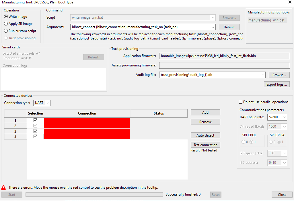
Manufacturing Tool
Use default arguments for the trust provisioning command.
Insert a smart card into your computer (if you have a built-in reader) or connect an external smart card reader. To find the connected smart cards, click the Refresh button. Verify, that production limit available on the smart cards is higher than number of connected processors.
Select the audit log file that is created during firmware provisioning. It is not allowed to use one log file for several smart cards. It is recommended to use one log file per a smart card.
For serial connection:
Adjust the baud rate, the default value is 115200; however, it was successfully tested baud rates up to 1000000.
Production steps:
Connect one or more processors via USB or serial line and click the Autodetect button to detect the connected devices. In case the tool detects devices, that should not be affected by the manufacturing, such as serial ports used by other devices, disable them. Then click Test connection below to check the connection with all enabled processors and ensure the test pass. The tool may contain several versions of the provisioning firmware for different silicon revisions. If the provisioning firmware is not autoselected, click the Test connection button provides detection of the silicon revision and assignment of the firmware.
To start the trust provisioning operation, click the Start button. Wait until all operations are finished.
Continue with step 1
The number of successfully provisioned devices is displayed on the bottom of the Manufacturing Tool window. This number is not 100% reliable, it is recommended to check remaining production limit reported for the connected smart cards.
After the production is done, click the Export logs button to export the log into the audit log package and send it to OEM.
If the trust provisioning operation fails, it depends on the status of the device, whether the next attempt can succeed. It is recommended to reset the device before the operation is repeated.
Audit log verification at OEM side
Audit log package contains:
Audit log, SQL lite DB, that is used for verification and contain certificates
LOGs from the manufacturing process, text files
To verify the audit log package, open the Smart card management view and ensure that the corresponding Production audit log key is selected.
If the audit log contains device identities, you can optionally export certificates generated for each device. In this case, configure the corresponding parameters (see the next chapter for details).
Click the Verify audit logs button and select the path to the received audit log ZIP package. After the verification is completed, find the detailed results in the LOG view.
Device identity and cloud service provider registration
IoT applications naturally rely on the services provided by the cloud for their operation; therefore, cloud services must have the means to verify the device identity against a known trusted source. OEM can prepare cloud infrastructure by pre-registering all device unique certificates if available, or by registering a single CA against which all devices are verified upon connection. In the latter case, the infrastructure verifies that the device unique certificates have been signed by the user-specified CA and automatically registers the devices.
Configure device identity
Trust provisioning capabilities in the Secure Provisioning Tool complement the just-in-time provisioning flow. The Device Identity Configuration window expects an OEM CA certificate as an input in the Issuer view, along with the list of X.509 attributes that define what unique device certificates must contain and where they must reside. During the manufacturing process, device-unique certificates are generated and signed in a secure way in the smart card by the CA. They can be installed in the desired location for use when interacting with the cloud. The certificates are generated in the X.509 format and during the device provisioning they are recorded into the audit log. When extracted from the audit log, they can be directly used within the cloud.
Some processors may support generation of the following certificate types:
CA: see USKS usage control property in the processor Reference Manual.
RTF: see URTF usage control property in the processor Reference Manual.
On the Smart card management view, go to the Smart card configuration section, enable Device identity and click the Device identity configuration… button.
In the configuration dialog, specify the number of device identity private/public key pairs to be generated during provisioning.
Specify the duration for generated certificates.
In the Certificate addresses section, specify the addresses where the corresponding certificates will be placed in the device NVM memory of the target processor.
In the Certificate fields section on the Subject view, you can optionally configure X.509 attributes for the device identity certificates. On the Issuer view, import the attributes for the device identity certificate signing key from the CA certificate or edit the attributes manually.
In the Smart card configuration section, specify the certificate signing key to be used for signing the generated device certificates.
The details about the information created in the flash during trust provisioning process can be found in SPSDK documentation, see main menu > Help > SPSDK Online Documentation.
Extract certificates from the audit log package
During verification of the audit log, it is possible to optionally extract device certificates. The NXP identity certificates are generated in the process of verifying that provisioning happens on a genuine NXP device. Typical use cases do not require their use; for example, registration of a device with a cloud provider can be done with the device identity certificates as described in the sections above.
You can use the Extract certificates checkbox to enable the feature. Select whether you want to extract device certificates only or also NXP identity certificates; the format of device identity certificates is selectable, while NXP identity certificates are always in binary form. Specify target directory, it must be always selected empty or new directory.
Deploy certificates
Before provisioned devices can interact with IoT cloud services, the CA should be registered with the cloud provider. The procedure varies across vendors. Find some useful resources below:
Amazon Web Services IoT:
Microsoft IoT Hub
Performance optimizations
The smart card manufacturing process consists of the following phases:
Loading provisioning firmware
Provisioning of the security assets using a smart card
Loading the application image
Phases 1 and 3 are executed in parallel, that’s why the operation with the smart card is limited to the number of available smart cards.
For an overview of how the number of smart cards affects the manufacturing time, here are examples of the total provisioning time for a small application (20 KB), measured on Ubuntu, with the processors connected via USB and 1 device certificate generated:
Number of LPC55S36 provisioned in parallel |
Number of smart cards |
Total provisioning time |
|---|---|---|
1 |
1 |
7 sec |
3 |
1 |
12 sec |
3 |
3 |
8.5 sec |
Debug authentication workflow
This section describes the process of opening the debug port. This tool offers Debug Authentication Protocol (DAP) as a mechanism to authenticate the debugger (an external entity) for the field technician, which has the credentials approved by the product manufacturer (OEM) before granting the debug access to the device. For Debug Authentication (DA) to work, processor-specific fuses or PFR fields must be set. For more information see the device user manual, chapter Debug subsystems.

Debug Authentification protocol usage example
To open the debug port, do the following:
Field Technician
Contact OEM to acquire the key type and the length of ROT. OEM decides whether to use the generated certificate for any device with the same ROT keys or just one by specifying the UUID.
In the SEC tool, create a workspace for the used target device, switch to the “PKI Management” view
Generate a debug key, the DA key type and the length must be the same as that of the ROT key
Create debug certificate request, specify UUID to limit use of debug certificate. If the UUID is set to zero it can be used for any device. UUID can be read from a device, via UART or USB if the device is in the development life cycle. Or via the debug probe when the device is in the advanced life cycle, on most devices CHECK_UUID must be set in the SOCU register/PFR field, for this option to work.
Send the certificate request to OEM
After the certificate from OEM is received, select Open debug port. Connected probes are detected upon dialog display. The list of detected probes can be updated by Find probes. Select one of the detected probes. The authentication beacon is in no way dependent on the credential beacon provided by the OEM. It is not interpreted by the debug authentication protocol, it is passed to the debugged application. When the dialog is confirmed, there is a script generated into workspace\debug_auth\open_debug_port.[bat|sh] and the script is executed. The dialog will be closed if no error is reported by the script (the operation is successful). In case of failure, refer to section Debug authentication in Troubleshooting for useful tips how to enable debug authentication.
Note: nxpdebugmbox CLI tool can be found in
<installation_dir>/tools/spsdk/folder
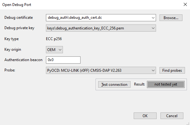
Dialog for opening debug port
OEM
Having the request received, click Generate debug certificate.
The certificate is by default generated into <workspace>/debug_authfolder, debug_auth_cert.dc. A *.zip folder with the same name is created, it contains the certificate and the .txt file note from OEM. The note that is passed from field technician to OEM is displayed in the note field (see Figure 72 “Generation of debug certificate from certificate request”).
SoC - mask value of
DCFG_CC_SOCUcontrolling which debug domains are accessed via the authentication protocolVendor usage - field that can be used to define a vendor-specific debug policy. The use case can be Debug Credential (DC) certificate revocations, the department identifier or the model identifier.
Credential beacon - value that is not interpreted by DAP, it is passed to the application. The value is independent of the authentication beacon that will be provided by the field technician when the port is opened.
Note - text field where OEM can describe comments about reasons to generate the certificate
Sign with ROT key - sign the certificate with one of the ROT keys that were used to secure the device.
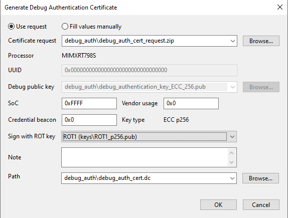
Generation of debug certificate from certificate request
Example of access rights to debug domains
Examples are intended for testing purposes. Before the final usage, the setting should be revisited and modified to fulfill security requirements. In all examples below, ISP is enabled and UUID check is disabled. For some processors, UUID check must be set to enable the read of UUID by a debug probe.
Table KW45xx/K32W1xx and MCX W71x
Fuse |
Everything disabled |
Everything enabled |
Controlled by DA |
|---|---|---|---|
DCFG_CC_SOCU_L1, DCFG_CC_SOCU_L2 |
0x000000FF |
0x0000FFFF |
0x00004040 |
DBG_AUTH_DIS |
0x0 |
0x0 |
0x0 |
Table LPC55S0x/1x, MCXW236 and NHS52S04
PFR field |
Everything disabled |
Everything enabled |
Controlled by DA |
|---|---|---|---|
DCFG_CC_SOCU_NS_PIN, DCFG_CC_SOCU_PIN |
0xFF2000DF |
0xFF2000DF |
0xFFBF0040 |
DCFG_CC_SOCU_NS_DFLT, DCFG_CC_SOCU_DFLT |
0xFFFF0000 |
0xFF2000DF |
0xFFBF0040 |
Table LPC55S2x
PFR field |
Everything disabled |
Everything enabled |
Controlled by DA |
|---|---|---|---|
DCFG_CC_SOCU_NS_PIN, DCFG_CC_SOCU_PIN |
0xFF2000DF |
0xFF2C00D3 |
0xFFBF0040 |
DCFG_CC_SOCU_NS_DFLT, DCFG_CC_SOCU_DFLT |
0xFFFF0000 |
0xFF2C00D3 |
0xFFBF0040 |
Table LPC55S3x
PFR field |
Everything disabled |
Everything enabled* |
Controlled by DA |
|---|---|---|---|
DCFG_CC_SOCU_NS_PIN, DCFG_CC_SOCU_PIN |
0xFE3001CF |
0xFE3001CF |
0xFFFF0000 |
DCFG_CC_SOCU_NS_DFLT, DCFG_CC_SOCU_DFLT |
0xFFBF0040 |
0xFE3001CF |
0xFFFF0000 |
Note For debugging, authentication is still required but the domain cannot be disabled by the SoC mask in the DAC.
Table LPC55S6x
PFR field |
Everything disabled |
Everything enabled |
Controlled by DA |
|---|---|---|---|
DCFG_CC_SOCU_NS_PIN, DCFG_CC_SOCU_PIN |
0xFD0002FF |
0xFD0002FF |
0xFFBF0040 |
DCFG_CC_SOCU_NS_DFLT, DCFG_CC_SOCU_DFLT |
0xFFBF0040 |
0xFD0002FF |
0xFFBF0040 |
Table MCX Nx4x and MCX N23x
PFR field |
Everything disabled |
Everything enabled* |
Controlled by DA |
|---|---|---|---|
DCFG_CC_SOCU_NS_PIN, DCFG_CC_SOCU_PIN |
0xF81007EF |
0xF81007EF |
0xFFBF0040 |
DCFG_CC_SOCU_NS_DFLT, DCFG_CC_SOCU_DFLT |
0xFFBF0040 |
0xF81007EF |
0xFFBF0040 |
Note For debugging, authentication is still required but the domain cannot be disabled by the SoC mask in the DAC.
Table RT5xx/6xx
Fuse |
Everything disabled |
Everything enabled |
Controlled by DA |
|---|---|---|---|
DCFG_CC_SOCU, DCFG_CC_SOCU_NS |
0x80FF408D |
0x80FFFF20 |
0x00404088 |
DCFG_CC_SOCU_AP |
0x7F00BF72 |
0x7F0000DF |
0xFFBFBF77 |
Table RW61x
Fuse |
Everything disabled |
Everything enabled* |
Controlled by DA |
|---|---|---|---|
DCFG_CC_SOCU, DCFG_CC_SOCU_NS |
0x3FFA007E |
0x3FFFFF14 |
0x1002000F |
DCFG_CC_SOCU_AP |
0xC005FF81 |
0xC00000EB |
0xEFFDFFF0 |
Note For debugging, authentication is still required but the domain cannot be disabled by the SoC mask in the DAC.
RT 118x does not have any fuse to control debugging rights. Debugging depends on the LC, for OEM_OPEN: all debug allowed, OEM_CLOSE: all closed but can be enabled by DAC, and OEM_LOCKED: all closed and cannot be enabled. The only way to manage debugging rights in OEM_CLOSE is by setting the SoC in DAC. For examples of SoC masks, see the device user manual.
Signature provider workflow
This section describes the process of setting up signature provider and building an image signed by the signature provider. There are examples of the signature provider server located in <install_folder>/bin/_internal/sample_data/signature_provider_examples, one working with ROT ECC keys and the other with ROT RSA keys. These examples demonstrate the full implementation of the API, however in the real world, it is expected the implementation will be changed by communication with HW HSM module or custom HTTPS communication to another server. Both examples of the server can be used as they are to test tool behavior when using the signature provider. Each server has example private keys and prepared public key response for the public_keys_certs endpoint. Prepared ECC/RSA public tree have 4 ROT keys/certs and each ROT key/cert has one IMG key/cert. These keys should not be used in final products.
The figure below displays variants of signature provider, SEC tool send requests to Custom signature provider HTTP server. This server should pass the request to one of the secure solutions and then pass the response back to the SEC tool. Prepared examples implement only the Custom signature provider HTTP server. The example server is doing all the operation that should be done by an HSM or external signature provider. It is up to the user to implement a complete solution.

Expected structure of signature provider
Run the server
Ensure python 3.12 or higher is installed. Open the directory where the server implementation and run the following commands:
# ensure, venv is installed
pip install virtualenv
# create virtual environment into .venv subfolder
python -m venv ".venv"
# activate it
.venv\Scripts\activate
# install all required packages into venv
pip install -r requirements.txt
# start the server
python server.py
The server logs every action, so it is possible to review what actions were executed.
Set up in the SEC tool
To use the signature provider example with the SEC tool, follow these steps:
Create/use workspace for the processor.
Select the check-box Use sign. provider on the PKI tab. If there are keys in the workspace, they are moved to a back-up subfolder in the workspace.
Open the signature provider dialog by clicking Configure… next to the check-box from step 2.
Review the default parameters of your signature provider, if using the signature provider server from
resources\signature_provider_examplesthe setting can be left as is.Select the prehash option in the parameters table. When prehash is enabled, only a hash of the data is sent to the server for signing.
Click the Test connection button to verify if the server is configured properly.
There are two options to Import public keys:
In the same dialog, click the Import public keys button to import public keys from the server; this is a recommended way, however it can be used only if the server implements optional API public_keys_certs.
If the Import public keys command is not supported, the alternative way is to use Import keys from the PKI management tab. Make sure that public keys match private keys that are used on the signature provider site (copy the keys to the folder with the signature provider example).
On the Build tab, select the key as normally, now the config files for SB, MBI, and certification block will be using the signature provider configuration.
Now, the signature provider is configured. It is possible to build a signed image.
Signature provider and debug authentication
The SEC tool supports signing of the DA certificate by the signature provider. However, the debug key pair generation is supported only locally. The field technician flow of the DA key generation is same as without the signature provider. The only difference is that in the DAC generation on the OEM site, the signature provider is used for signing. This is transparent to the user as the public key is selected from the workspace keys. The only difference is in the generated configuration file, where the sign_provider field is set according to the signature provider setting.
Script hooks
Script hooks are executed before or during build, write, and manufacturing script execution. Script hooks enable script customization outside the generated scripts. Script hooks are re-generated only on explicit request. Hook scripts are located in the “hooks” subfolder and new workspace contain the examples for the selected processor. In GUI, the hook script is created by a single click.
Build script hooks
Pre-build hook:
pre_build_<os-name>.bat/shis executed before the build script. This script can be generated to sign the MCUboot application image. This script does not have any argument and it is called only from GUI before the build script is executed.Build hook:
build_<os-name>.bat/shis called after every main step in the build script. This script is called from the build script and the name of the previous step is passed as an argument. All the supported steps are handled in the generated examples. In case a hook step call ended in failure, the build script execution stops and exits with an error.
Write script hooks
Write hook: write_<os-name>.bat/sh is called after every main step in the write script. The script is called from the write script and the name of the previous step is passed as an argument. All the supported steps are handled in the generated examples. In case the hook step call ended in failure, write script execution will stop and exit with an error.
Manufacturing hooks
Manufacturing hook: manufacturing_<os-name>.bat/sh is called at the beginning and end of the manufacturing process before the first task is started and after the last task is finished. If manufacturing hook execution for step started fails, planned manufacturing steps are not executed. The call for step finished has an additional argument status that can have two values ok or fail that denote the execution status of the manufacturing process: ok if all tasks were finished successfully, fail otherwise.
Typical usage
Here are a few examples how the hook scripts can be used to customize the build, write, or manufacturing script without the modification of the script generated from the SEC tool:
Update the input source file(s) for the build.
Fix the problem in the write script or apply an additional action that updates the previous action.
Synchronize the manufacturing operation with the assembly line.
Manufacturing workflow
For the manufacturing operations, the tool offers a simplified user interface focused on the manufacturing only.
Create manufacturing package
OEM can create a manufacturing package (*.zip) that can be used to transfer files to the factory. In the factory, the tool creates a manufacturing workspace by importing the manufacturing package. The manufacturing package can be created:
On the Write image view - for provisioning using the current write script
On the Smart card management view - for provisioning using the smart card
In the SB editor - to apply commands specified in the SB file
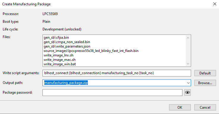
Create Manufacturing Package dialog
The Create Manufacturing Package dialog allows the user to:
Review files included in the package.
Check the write script arguments, the arguments are in the same format as they are used in Manufacturing Tool.
Select the output manufacturing package file path.
Set the password for the zip file. The AES algorithm is used to encrypt files in the zip file; however, the file metadata (like file names and file sizes) are not encrypted.
For the EdgeLock 2GO provisioning, it is possible to optionally specify the API key in the manufacturing package, but it can be specified later during manufacturing
Performance optimization
It is supposed that the provisioning/write script will be executed several times to address different development issues, so the script is designed primary for this use case and may contain some parts that are not necessary in manufacturing when the provisioning is applied to an empty processor. Here are some tips to improve manufacturing performance by manually modifying the generated script:
It might not be needed to erase boot memory. If the processor is new, the flash is already erased.
It might not be needed to detect if the chip is already secured; this part in the write script allows updating application for secured processors (for chips where it is supported)
A longer sequence of blhost operations might not be optimal, because the blhost initialization time is not insignificant. It might be better to move the operations into the SB file (see SB editor) or use blhost batch command (see SPSDK documentation for details).
For processors with device HSM, consider moving all actions into the device HSM SB file including the application image.
If the processor is reset during manufacturing, there is a delay time until it boots and the OS driver reconnects. By default it is 3 seconds. The time can be adjusted in preferences.
Manufacturing operations
On the manufacturing site, the manufacturing package can be imported using main menu > File > Import Manufacturing Package…. During import, the files from the package are extracted into the new workspace. For more information about importing package, see Import workspace from the ZIP.
Once the workspace is created (or reopened), the Manufacturing Tool (for details, see Manufacturing Tool ) is displayed, and the rest of the tool functionality is not available. If the Manufacturing Tool is closed, the whole tool operation is finished. If you restart the tool, it offers to continue manufacturing, or to select another workspace:
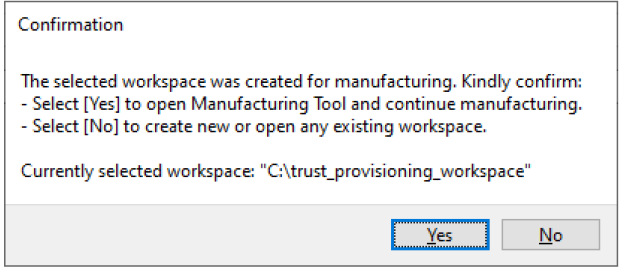
Confirmation to reopen manufacturing
If the manufacturing package contains a write script, check if the SPT_INSTALL_BIN environment variable in the script points to the installation directory on the computer. If not, it is recommended to set the environment variable globally or update the write script manually. The manufacturing process is analogical to the one described in Factory: Manufacturing process. It is supposed to be applied on new/empty processors.
MCUboot workflow
MCUboot is an open source secure bootloader for 32-bits microcontrollers. For details, see https://docs.mcuboot.com/. It has been ported to many NXP processors, and you can find it supported in the MCUXpresso SDK. For details, see boards\<board>\ota_examples\mcuboot*.
In the SEC tool, MCUboot is supported for all processors, where “Additional Images” are supported. See the “Features” excel spreadsheet attached to this document for details.
For most of the processors, the SEC tool contains a default configuration compatible with project examples provided in the MCUXpresso SDK. Therefore, there is a “sample application” built from MCUXpresso SDK for the EVK/FRDM board and the default imgtool parameters match MCUXpresso SDK. See the “Features” excel spreadsheet attached to this document for details.
Steps to start MCUboot with such a processor:
Create a new workspace for the selected processor.
Connect the board via UART, ensure the processor boot is in ISP mode, and check the connection (main menu > Target > Connection…). It is possible to use other connections, the UART is used because the mcuboot application is built with the debug console and prints the status that can be verified using the terminal.
Verify the selected boot memory in main menu > Target > Boot Memory …. For MCX N series, IFR must be used.
On the Build image view, select the “mcuboot opensource” application as “Source executable image”. The prebuilt application is available in
sample_data\targets\<processor>\source_images\<board>_mcuboot_opensource.s19. You can also build your own from MCUXpresso SDK. If the application contains a configuration of the external flash (FCB), the tool detect and offers to use it. It is recommended to accept.Open main menu > Tools > MCUboot > Sign Image and configure the following:
The secondary application to be signed; the prebuilt application is available in
sample_data\targets\<processor>\source_images\<board>_ota_mcuboot_basic.s19The signing key; it is located in the same folder that the prebuilt application or in MCUXpresso SDK, in folder
boards\<board>\ota_examples\mcuboot_opensource\keys\. Depending on the platform. use eithersign-rsa2048-priv.pemorsign-ecdsa-p256-priv.pem. Keys protected by a password are not supported yet.The imgtool arguments by default should match the SDK example. It is not needed to change them.
Click the Sign button to sign the application; fix problems, if any.
Ensure that the check boxes below are selected:
the first check-box: the tool creates the pre-build hook script that signs the application before each build
second check-box: the tool reconfigures additional images, so the signed image is written to the target address; keep “Image 1”
Verify the target address of the application.
Close the dialog by clicking the Save & Close button.
On the Build tab, double-check that the Build script hooks section contains the pre-build script.
Open Additional Images and check that the signed application is properly configured as “Image 1”.
Build and write the bootable image into the processor.
Open a terminal (in MCUXpresso IDE go to main menu > Windows > Show View > Other > Terminal), select the UART port, confirm, and reset the processor. You should receive the following text:
hello sbl.
Bootloader Version 2.0.0
Primary   slot: version=1.0.0+0
Image 0 Secondary slot: Image not found
writing copy_done; fa_id=0 off=0xfffd0 (0xfffd0)
Image 0 loaded from the primary slot
Bootloader chainload address offset: 0x0
Reset_Handler address offset: 0x400
Jumping to the image

Booting the primary slot - flash remapping is disabled

*************************************
* Basic MCUBoot application example *
*************************************
Built Apr 16 YYYY 12:34:56
To sign and write a second copy of the application, follow additional steps:
Disconnect the terminal if it is still open. Reset the board to ISP mode.
Open again main menu > Tools > MCUboot > Sign Image…
Keep the same input application image.
Change the output image name, for example add suffix 1_1
In imgtool arguments, change version to 1.1
In the Set additional image section change:
Image 2
Target address - increase the address by the slot size (see the slot size parameter in the imgtool arguments)
Save and Close.
Note: The pre-build script will be overwritten and it will sign Image 2. The previously signed Image 1 remains on the disk untouched and it will be written to flash at the original location.
Open Additional Images and check that there are two applications: “Image 1” and “Image 2”.
Build and write.
Connect the terminal, switch the board to boot from the selected boot memory, and reset. The terminal should receive the following text:
hello sbl.
Bootloader Version 2.0.0
Primary   slot: version=1.0.0+0
Secondary slot: version=1.1.0+0
writing copy_done; fa_id=1 off=0xfffd0 (0x1fffd0)
Image 0 loaded from the secondary slot
Bootloader chainload address offset: 0x100000
Reset_Handler address offset: 0x100400
Jumping to the image

Booting the secondary slot - flash remapping is enabled

*************************************
* Basic MCUBoot application example *
*************************************

Built Apr 16 YYYY 13:24:56
EdgeLock 2GO Trust Provisioning workflow
EdgeLock 2GO is a fully managed cloud platform operated by NXP that provides secure provisioning services for easy deployment and maintenance of IoT devices using supported NXP products. The service allows creating and managing secure objects, such as symmetric keys, key-pairs, and certificates that are then securely provisioned into your NXP MCU or MPU.
EdgeLock 2GO flow, high-level description
The figures below correspond to the sequence of actions indicated on Figure 77 “EdgeLock 2GO Trust Provisioning workflow”.
Configuration process
OEM prepares a secure configuration and verifies it locally. Then the SEC tool provides all secure objects, and the OEM uploads them via the EdgeLock 2GO web portal.
Manufacturing process
The tool fetches the processor UUID
The tool requests secure objects for the given UUID. The EdgeLock 2GO server validates UUID, generates secure objects, and encrypts them with EdgeLock 2GO root of trust. Secure objects are downloaded to the manufacturing machine.
Secure objects and EdgeLock 2GO provisioning firmware are loaded to the target processor. The firmware is invoked to install the secure objects into the target location. The application image is applied into the target boot memory.

EdgeLock 2GO Trust Provisioning workflow
EdgeLock 2GO flow, step by step
To configure EdgeLock 2GO provisioning, do the following steps:
Turn on secure boot mode and verify that the application works properly.
On the EdgeLock 2GO server, create the device group for the product and create an API key. For details, see EdgeLock 2GO Configuration via web portal.
In the main menu > Target > Trust Provisioning Type, select EdgeLock 2GO. Fill the EdgeLock2GO parameters and Test connection to the server.
Install the GnuPG tool and take advantage of the prepared encryption script.
OS-specific notes:
Windows - Kleopatra for Windows is recommended \ https://www.gpg4win.org/get-gpg4win.html. The encryption can also be done both manually using “Kleopatra GUI”. See EdgeLock 2GO Quick Start Guide (document AN13255 (The document is available upon request)) or using the way described above (GnuPG utilities are installed with gpg4win).
Ubuntu - use the gpg package in the Ubuntu repositories.
macOS - gnupg available in the brew package system is a recommended option; GnuPG for OS X should also work (see https://gnupg.org/download/ )
Steps needed to enable the GPG encryption in the build script:
The encryption is done in the
el2go/encrypt_el2go_files.*script generated into the workspace. Use the Update files button on the Build page to update the script.Import the EdgeLock 2GO public key for encryption, see the generated script for how to do it
Generate RSA key pair for signing - gpg –full-generate-key. Use 2048 or 4096 key size.
Set environment variables
EL2GO_GPG_PASSWORD - password for the generated key pair
EL2GO_GPG_SIGN_KEY - identify which key should be used for signing using key ID available by gpg–list-secret-keys. If the EL2GO_GPG_SIGN_KEY environment variable is defined, the encryption is invoked from the build script as a part of the build action.
Ensure that the development life cycle is selected in the main menu > Target > Life Cycle. For development purposes, the EdgeLock 2GO verification is supported with the open life cycle. This is not intended for production.
On the build page, click Build image to build the application. Ensure that there are no errors.
Open the
<workspace>/el2go/publishsubfolder and upload all secure assets into the EdgeLock 2GO server. Follow the instructions provided in EdgeLock 2GO Configuration via web portal.Note: Files for the EdgeLock 2GO server are also displayed on the build page. In the generated files, they are marked by the el2go cloud icon. The description is displayed in the tooltip.
Go to the Write page and run the Write operation.
If everything works as expected, set the deployment life cycle and repeat steps 7-9.
Create the manufacturing package. For details, see Create manufacturing package. For API key distribution, see API key to access EdgeLock 2GO server.
For processor-specific information, see Processor-specific workflows.
API key to access EdgeLock 2GO server
For development, the API key must be specified in the Trust Provisioning Type dialog.
For the manufacturing package, the API key can be specified optionally; if it is specified, it is recommended to encrypt the package with a password to protect the access.
If the API key is not specified in the manufacturing package, it can be specified in the manufacturing dialog or via the environment variable SEC_EL2GO_API_KEY.
For EdgeLock 2GO trust provisioning, the following access needs to be enabled for the manufacturing API key on EdgeLock 2GO server:
View - View device groups
General - Register devices
Remote trust provisioning - View secure objects and their intermediate CAs
EdgeLock 2GO Configuration via web portal
EdgeLock 2GO web portal URL: https://edgelock2go.com
An Application Note with detailed information about the EdgeLock 2GO configuration is planned to be issued. Until the document is available, use the information in this chapter.
How to create device group
Devices > New Device Group
Assign any name
Hardware family type: MPU and MCU
Hardware option: product name
Hardware type and product name: select a processor by name
How to create RKTH secure object
Secure Objects > New Secure Object
Select type: OEM FW Authentication Key Hash
Assign any name
Provide a binary file: <upload the file>
Usage policies: add a custom policy. Select the Open or Closed/Locked policy. Open is used for development and testing, Closed and Closed/Locked are used for production. The policy is to be aligned with the life cycle selected in the tool. For details, see processor-specific recommendations.
How to create CUST-MK-SK secure object
Secure Objects > New Secure Object
Select type: OEM FW Decryption Key
Assign any name
Provide the key material (.asc): provide a signed and encrypted key. It is generated by a SEC tool via GnuPG.
Provide the public key to use it for verifying the signature of the encrypted key. (.asc): your public key
Usage policies: same as RKTH; the policy must be same for all secure objects used in one device group.
Other secure object
See processor-specific information in Processor-specific workflows.
Merge Images Tool workflow for MIMXRT595
This section describes one specific use case for merging two separate images for MIMXRT595 as a single merged image. The output merged image will be signed during the build process. This section is written for MCUXpresso IDE with the Trust zone hello world SDK example, which contains two separate projects *hello_world_s and *hello_worlds_ns linked together. It is necessary to remove the link between the projects (MCUXpresso IDE) to generate two images instead of one image merged during the build process.
Remove linking between both projects by selecting the non-secured project *hello_world_ns go to Project > Properties > Project References and unchecking the *hello_world_s from the references.
Build both projects without any modifications
This example uses .s19 files so the final .axf files need to be converted. To do so, go to the Debug folder for both projects > right-click the generated *hello_world_ns.axf file >, choose Binary Utilities, and select Create S-Record.
How to merge both images:
Open the Merge tool by selecting Tools in toolbar > Merge Tool
Select evkmimxrt595_hello_world_s.s19. The target address will be automatically set to 0x18001000 (secured memory area)
For MIMXRT595 processors, only the non-secured address can be written by the user. The given address of the first image is in the secured memory map. Change the target address of the first image to 0x08001000 (non-secured memory area)
Select evkmimxrt595_hello_world_ns.s19. The target address will be automatically set to 0x08100000 (non-secured memory area)
Check the “Apply the merged images as the Source executable image on Build image view” checkbox
Leave the rest as it is and press the OK button
Check that the image is automatically applied as a Source executable image and its start address is updated as well
To sign and build the merged image, see the Booting signed image using shadow registers section, but use merge image as a Source executable image instead.