Working with the chip-tool-web2
The chip-tool-web2 is a web-based graphical user interface (GUI) for the Matter controller, designed specifically for i.MX SoC customers. It provides an intuitive interface for commissioning Matter devices, sending Matter messages and performing other Matter-specific actions.
With the chip-tool-web2, you can easily configure, manage, and monitor Matter devices without the need to use complex command lines.
Source files
You can find the source files for the chip-tool-web2 in the ${matter}/examples/chip-tool/webui-2_0 directory, which are separated into frontend and backend components. This allows easy customization and modification based on specific requirements and use cases.
Building and running the chip-tool-web2
Before using the chip-tool-web2, you must compile it from source on Linux.
Note: To ensure compatibility, you should always build the
chip-tool-web2from the same revision of theconnectedhomeiprepository.
Building the chip-tool-web2
The steps to compile the chip-tool-web2 are the same as How to build Matter application.
After compilation, you will find two binaries, chip-tool and chip-tool-web2, in the ${matter}/out/chip-tool-web2/ folder. However, note that the chip-tool binary in this folder may not work as expected. Therefore, it is recommended not to use the chip-tool binary located in the out/chip-tool-web folder.
Running the chip-tool-web2
Introduction
Before using chip-tool-web2, make sure that the i.MX board is properly connected to the Internet.
Default Setup
The image built by meta-nxp-connectivity includes the chip-tool binary in the i.MX SoC /usr/bin directory, and all frontend files are already copied to /usr/share/chip-tool-web/frontend2. Therefore, to use chip-tool-web2, you only need to copy the newly compiled chip-tool-web2 binary to the /usr/bin directory.
Custom Setup
If you want to specify a custom location for the frontend files, you can follow these steps:
Copy the
frontend2file to the desired location:$ cp ${matter}/examples/chip-tool/webui-2_0/frontend2 $frontend_pathExport the
CHIP_TOOL_WEB_FRONTENDvariable and set it to the path of the frontend files:$ export CHIP_TOOL_WEB_FRONTEND=$frontend_path
If you want to make this variable persistent across sessions, add the above command to your shell configuration file (for example,
~/.bashrc).
Verification
After completing the setup, run the following command to verify that chip-tool-web2 is working properly:
$ chip-tool-web2
If you see the following logs: CHIP:DL: CHIP task running and CHIP:TOO: LWS_CALLBACK_ESTABLISHED, everything is working fine.
Accessing the chip-tool-web2
The chip-tool-web2 can run on various devices, including desktops, laptops, and mobile devices. To access the chip-tool-web2, follow these steps:
Open a web browser (such as Chrome, etc.) on the device you want to use.
Enter the IP address of the i.MX board followed by
:8889in the address bar of the browser. You can find the IP address of the i.MX board by running theifconfigcommand on the board.You will see the
chip-tool-web2home page. Follow the instructions in the section to proceed.
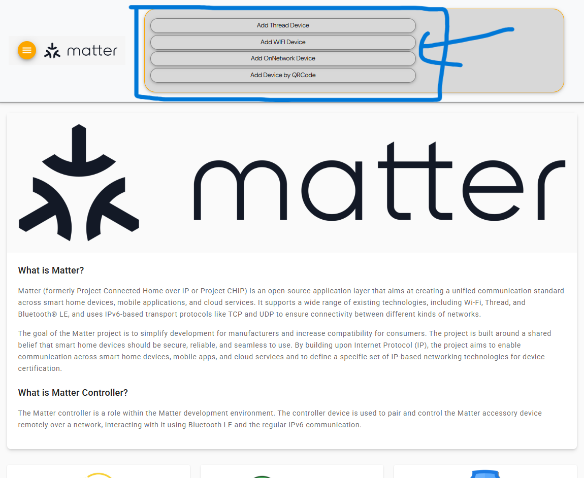
Example of opening on Windows
Here is an example of opening chip-tool-web2 on Windows using Chrome:
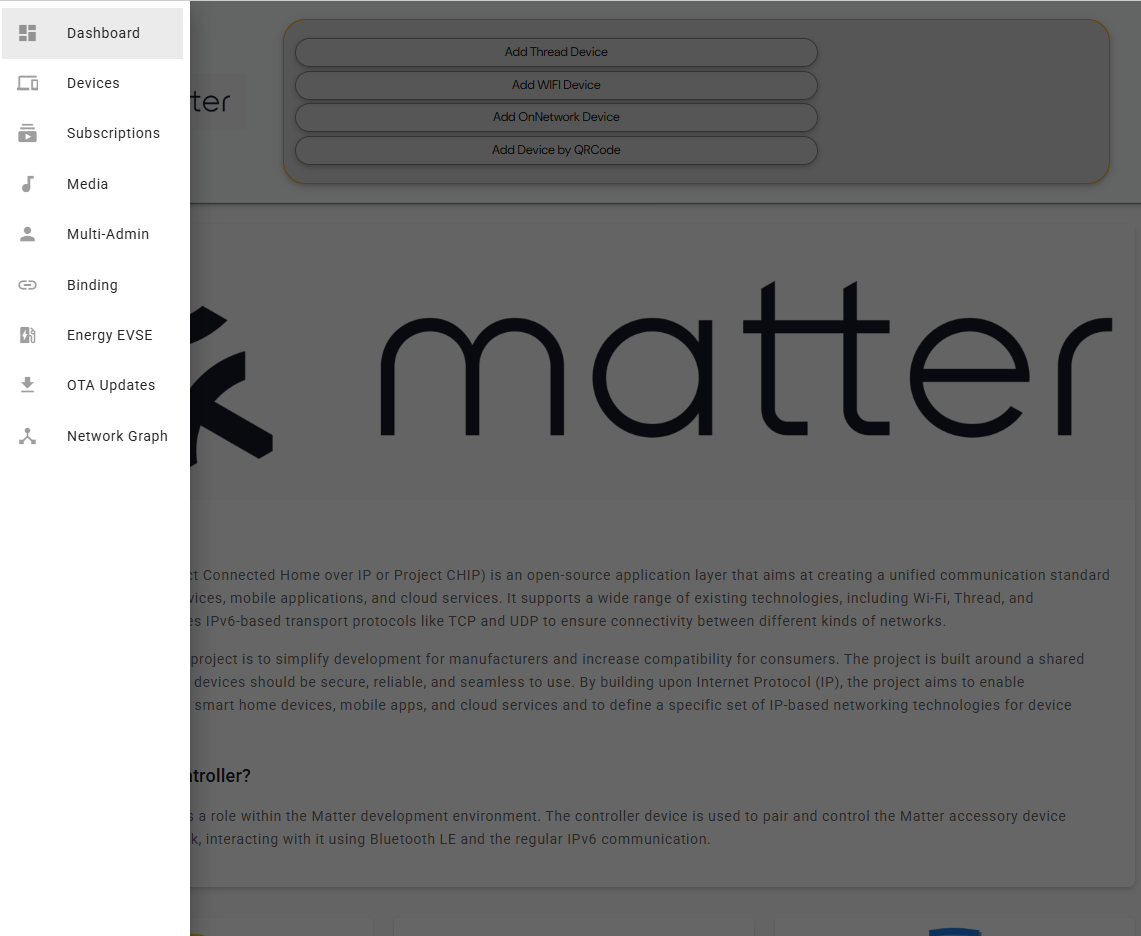
You can open the navigation sidebar from the Home page by clicking the navigation button in the upper‑left corner. The navigation sidebar is shown as follows.
Note: The network connected to the running device must be on the same segment as the i.MX device.
Using chip-tool-web2 to commission a Matter device
This section provides instructions for using chip-tool-web2 to commission Matter devices, with a focus on the chip-lighting-app application clusters on i.MX MPU platforms.
It should be noted that while chip-tool-web2 provides a graphical user interface (GUI) for executing commands through buttons and other visual controls, it does not completely replace the chip-tool command line tool. Users can still use the chip-tool command line tool if they prefer or need to, but chip-tool-web2 provides an additional option for interacting with Matter devices. The following sections provide a detailed overview of the features currently available in chip-tool-web2.
An official Matter document explaining how to use a chip-tool as a Matter controller, can be found here.
For more information on how to use Matter applications on i.MX MPU platforms, see the NXP Matter demos guide.
Using Interactive mode
The chip-tool offers two modes of operation: Single Command Mode and Interactive Mode, each with unique features and appropriate use cases. For detailed information about these modes, refer to the official documentation available at Interactive mode versus single-command mode.
It should be noted that chip-tool-web2 uses the Interactive Mode to allow users to conveniently send multiple commands through the web interface and to improve the management of Matter devices.
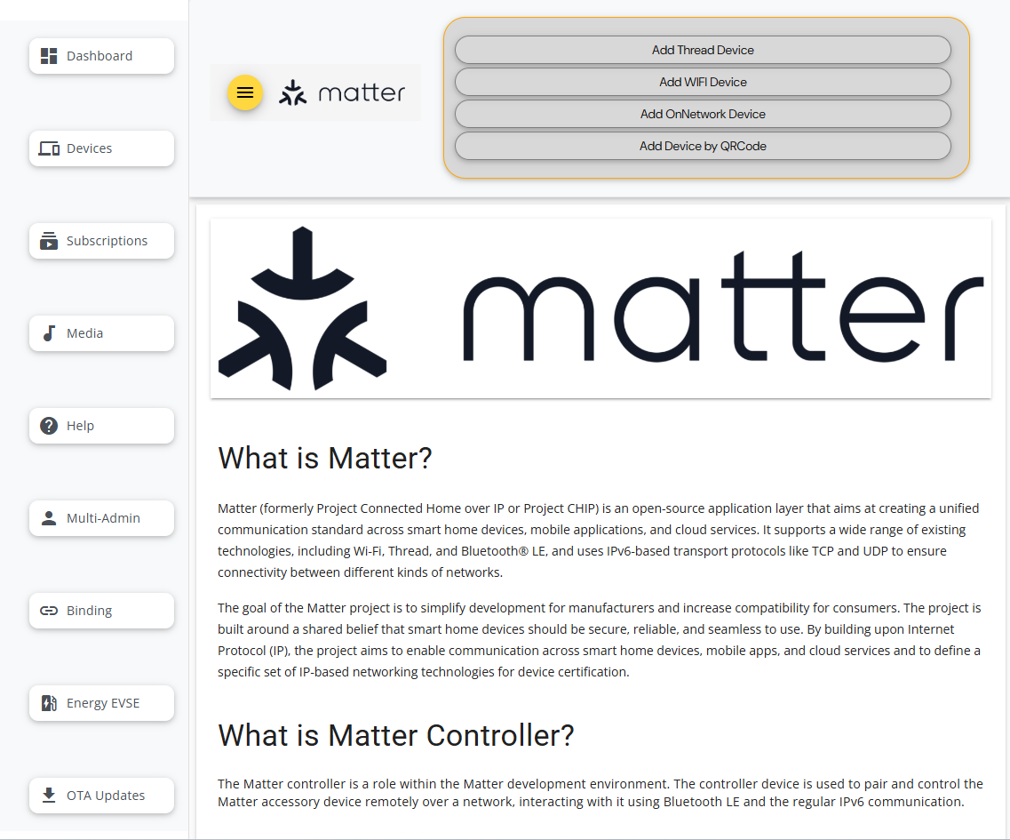
Commissioning a Matter device
The chip-tool-web2 supports four commissioning types: “Add Thread Device”, “Add WIFI Device”, “Add OnNetwork Device”, and “Add Device by QRCode”. You can start commissioning by clicking the corresponding buttons in the GUI header to start commissioning.
Add Thread Device
Click the Add Thread Device button. Enter the Device ID, Device Code, Device Alias, and Device Bluetooth Discriminator. Then, click the Get Dataset button to get the Open Thread dataset (Make sure that you run the otbr-agent in the i.MX device and the wpan0 interface is up before getting the dataset). Then you can click the Send Command to trigger the command to commission the device to the existing Thread network:
$ chip-tool pairing ble-thread <node_id> hex:<dataset> <pin_code> <discriminator>
In this command:
<node_id> is the user-defined device ID of the node being commissioned.
<dataset> is the Operational Dataset.
<pin_code> and <discriminator> are device-specific keys.
Note: When entering the <dataset>, there is no need to add the
hex:prefix, as this is already added by default in the chip-tool-web backend.
To obtain the Open Thread dataset, you can either form the OpenThread network manually by following the instructions provided in the Configure OpenThread Network, or via otbr-web.
Add WI-FI Device
Click the Add WIFI Device button. Enter the Device ID, Device Code, Device Alias, Network SSID, Network Password and Device Bluetooth Discriminator. Then, click the Send Command to trigger the command to commission the device to the existing Wi-FI network:
$ chip-tool pairing ble-wifi <node_id> <ssid> <password> <pin_code> <discriminator>
In this command:
<node_id> is the user-defined device ID of the node being commissioned.
<ssid> and <password> are credentials.
<pin_code> and <discriminator> are device-specific keys.
Add OnNetwork Device
Click the Add OnNetwork Device button. Enter the Device ID, Device Code, Device Alias. Then, click the Send Command to trigger the command to discover devices and attempt to pair with the first discovered one using the provided setup code:
$ chip-tool pairing onnetwork-commissioning-mode <node_id> <pin_code>
In this command:
<node_id> is the user-defined device ID of the node being commissioned.
<pin_code> is device code and specific _setup PIN code.
Add Device by QRCode
Add a device by QRCode support for pairing a new end device by scanning the QRCode. It also supports pairing with a multi-admin device when the commissioning window is enabled by ECM.
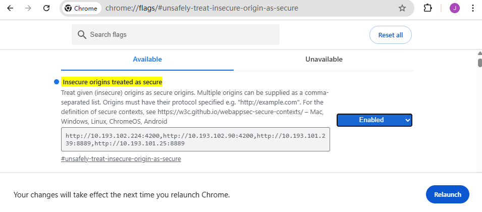
If you need to use the camera to scan the QR Code, you need to search for “chrome://flags/#unsafely-treat-insecure-origin-as-secure” in Chrome. Then, enter the “http://ip:port” and relaunch the browser like below:
Then, click the Scan QR Code and Start Scan buttons. A window will pop up. Choose the “Allow while visiting the site” for camera permission for QR Code scanning.
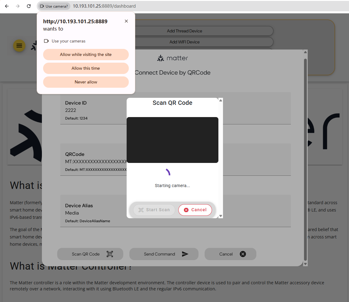
After scanning the QRCode, the web interface will update the QRcode input field. Then, enter the Device ID and Device Alias, and click the Send Command to pairing device by QRCode. The following command is triggered to commission the device:
$ chip-tool pairing code <node_id> <payload>
In this command:
<node_id> is the user-defined device ID of the node being commissioned.
<payload> is the scanned QR Code, or enter the payload by yourself.
Note: The QRCode Scanning feature is only supported on Chrome for Windows and Android. It is not supported on iOS because Chrome on iOS does not allow setting chrome://flags.
List commissioned devices in chip-tool-web2
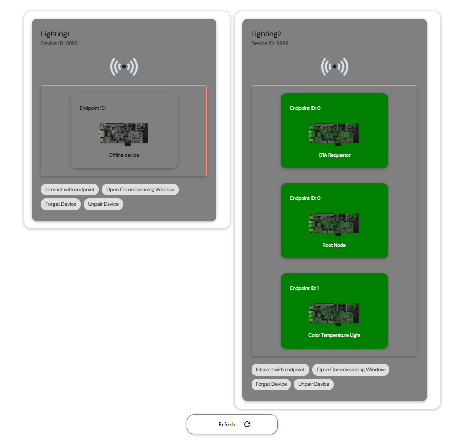
Once the pairing process is complete, the Matter device is successfully commissioned to the network. To view all commissioned devices, click the Devices button in the sidebar. Each device card displays the following information:
Node Alias (for example, “Lighting1” and “Lighting2”)
Device ID (for example, “8888” and “9999”)
Endpoint Details, such as the “Color Temperature Light” cluster on endpoint ID 1
If a device goes offline, it is labeled as “Offline device”, as shown below.
Interact with lighting device
Click the Interact with endpoint, and enter Endpoint ID, and then select ON, OFF, Toggle, or Read to interact with the lighting device.
Use the
ONbutton to trigger the following command to turn on the state of the OnOff attribute:$ chip-tool onoff on <node_id> <endpoint_id>
Use the
OFFbutton to trigger the following command to turn off the state of the OnOff attribute:$ chip-tool onoff off <node_id> <endpoint_id>
Use the
Togglebutton to trigger the following command to toggle the state of the OnOff attribute:$ chip-tool onoff toggle <node_id> <endpoint_id>
Use the
Readbutton to trigger the following command to read the state of the OnOff attribute:$ chip-tool onoff read on-off <node_id> <endpoint_id>
In the above commands:
<node_id> is the user-defined device ID of the commissioned node.
<endpoint_id> is the ID of the endpoint with OnOff cluster implemented.
Open Commissioning Window
For the open commissioning window, refer to the multi-admin section.
Forget Device
To remove an offline device, click the “Forget Device” button on its card. A confirmation dialog appears. Click “Forget Device” again in the dialog to proceed.
If the operation is successful, a confirmation message is displayed. To reflect the changes, click the “Refresh” button to update the device list.
Unpair Device
To unpair an online device, click the “Unpair Device” button on its card. A confirmation dialog appears. Click “Unpair Device” again in the dialog to initiate the unpairing process.
Upon success, a confirmation message is shown. Click the “Refresh” button to update the device list accordingly.
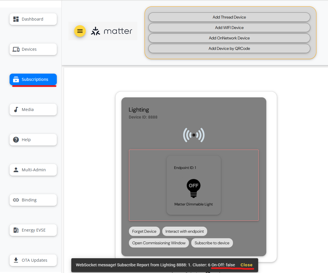
Subscription of Matter device OnOff cluster in chip-tool-web2
Subscribing to an attribute lets you mirror the state of the attribute as it changes in the Matter network. Chip-tool-web2 support for subscribing to the on-off attribute of the onoff cluster. Click the Subscriptions button in sidebar to see all the commissioned devices. Click the Subscibe to device in device card, enter the Endpoint ID, Subscription Min Interval, Subscription Max Interval. Select Cluster ON/OFF and then click Subscribe button to trigger the subscribe command.
$ chip-tool onoff subscribe on-off <min-interval> <max-interval> <node_id> <endpoint_id>
In this command:
<min-interval> specifies the minimum number of seconds that must elapse since the last report for the server to send a new report.
<max-interval> specifies the number of seconds that must elapse since the last report for the server to send a new report.
<node-id> is the user-defined device ID of the commissioned node.
<endpoint_id> is the ID of the endpoint where the
onoffcluster is implemented.
Note: Because subscribe must maintain the subscription status in interactive mode, please do not enter any other commands in the console of the i.MX Matter devices when the chip-tool-web2 initiates the subscribe command, as this may interrupt the update of the subscribe report.
The subscription information appears at the bottom of the interface as shown below:
Controlling a Matter device media playback cluster
The i.MX Matter supports the nxp-media-app from the 2023 q4 release. You can use chip-tool-web2 to control the media player and read information.
Click the Media button in the sidebar. The following interface is displayed:
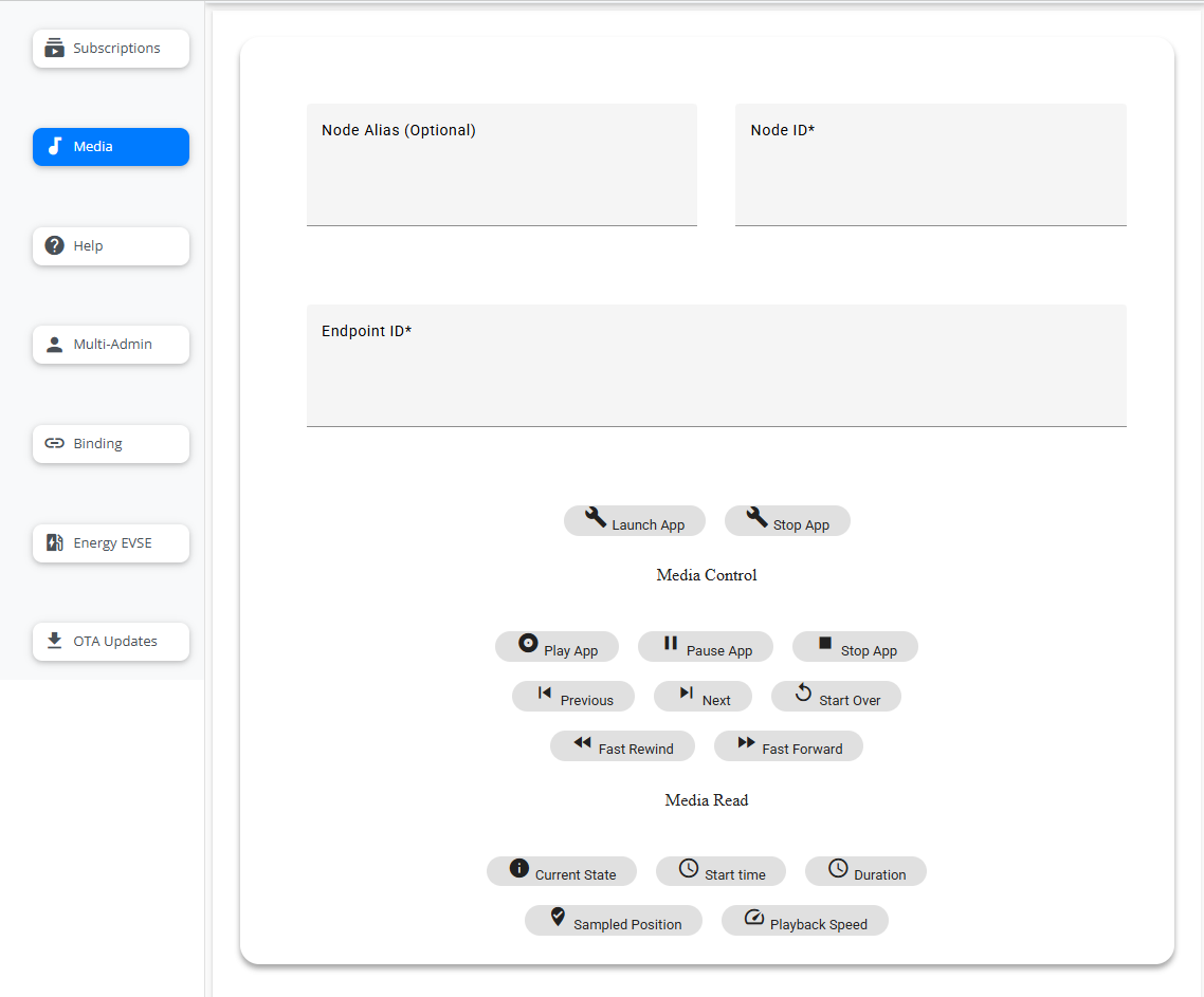
Note: Before controlling media app, you need to place media files in the
/home/root/mediafolder of device, which is running the nxp-media-app.
Launch or Stop app
Enter the Device Alias, Device ID, and Endpoint ID. Then, you can click the Launch APP or Stop APP button to launch or stop the app.
Playback Control
Enter the Device Alias, Device ID, and Endpoint ID. Then, use the following buttons in the Playback Control section to control the status of the mediaplayback attribute:
Use the
Playbutton to trigger the following command to change the current media playback state to play:$ chip-tool mediaplayback play <node_id> <endpoint_id>
Use the
Pausebutton to trigger the following command to change the current media playback state to pause:$ chip-tool mediaplayback pause <node_id> <endpoint_id>
Use the
Stopbutton to trigger the following command to change the current media playback state to stop:$ chip-tool mediaplayback stop <node_id> <endpoint_id>
Use the
Previousbutton to trigger the following command to play previous media:$ chip-tool mediaplayback privious <node_id> <endpoint_id>
Use the
Nextbutton to trigger the following command to play next media:$ chip-tool mediaplayback next <node_id> <endpoint_id>
Use the
Start Overbutton to trigger the following command to start over the media being played:$ chip-tool mediaplayback start-over <node_id> <endpoint_id>
Use the
Rewindbutton to trigger the following command to rewind the current media, and then you can use thePlaybutton to play the rewinded media:$ chip-tool mediaplayback rewind <node_id> <endpoint_id>
Use the
Fast Forwardbutton to trigger the following command to fast forward the current media:$ chip-tool mediaplayback fast-forward <node_id> <endpoint_id>
In the above commands:
<node_id> is the user-defined ID of the commissioned node.
<endpoint_id> is the ID of the endpoint with
mediaplaybackcluster implemented.
Media Information
Enter the Device Alias, Device ID, and Endpoint ID. Then, use the following buttons to read the status of the mediaplayback attribute in the Media Information section.
Use the
Current Statebutton to trigger the following command to read the current state of media playback:$ chip-tool mediaplayback read current-state <node_id> <endpoint_id>
Use the
Start timebutton to trigger the following command to read the start time of the currently playing media:$ chip-tool mediaplayback read start-time <node_id> <endpoint_id>
Use the
Durationbutton to trigger the following command to read the duration of the currently playing media:$ chip-tool mediaplayback read duration <node_id> <endpoint_id>
Use the
Positionbutton to trigger the following command to read current sampled position playback speed of the currently playing media:$ chip-tool mediaplayback read sampled-position <node_id> <endpoint_id>
Use the
Playback Speedbutton to trigger the following command to read the playback speed of the currently playing media:$ chip-tool mediaplayback read playback-speed <node_id> <endpoint_id>
In the above commands:
<node_id> is the user-defined ID of the commissioned node.
<endpoint_id> is the ID of the endpoint with mediaplayback cluster implemented.
Report Format
The media read report is output in text format with the following structure:
Report from ${nodealias} ${nodeid}:${endpoint}. Cluster:${cluster}
${attribute}:${value}
In the structure above,
${nodealias}: The node alias of the device.
${nodeid}: The nodeid of the device.
${endpoint}: The endpoint of the device.
${cluster}: The cluster name to which the device belongs.
${attribute}: The name of the attribute being reported. In this case, the default attributes are
CurrentState,StartTime,Duration,Sampled Position,PlatbackSpeed.${value}: The value of the attribute. There are three possible values for
CurrentState:Play,Pause,Stop. The value of start time is always0. The value ofDurationis currently playing media’s duration. There are five possible values forPlatbackSpeed:1.000000,2.000000,4.000000,8.000000,10.000000.
Binding for light and switch Matter device
Binding describes a relationship between the device that contains the binding cluster and the end device. The chip-tool-web2 supports binding a light in one light_switch_combo device to the switch in another light_switch_combo device, allowing the light in another device to be controlled by the switch of one device.
To access the Binding function in the chip-tool-web2, click Binding button on sidebar. The following interface is displayed:
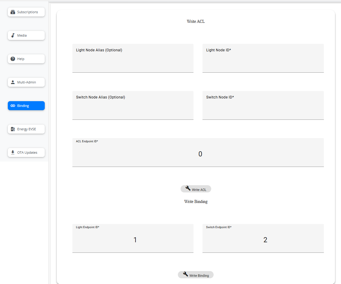
Write ACL
First, the light_switch_combo application should run properly on the K32W Matter device, and then use the chip-tool-web2 ble-thread pairing method to commission with two light_switch_combo devices separately.
Two light-switch_combo devices, one used as the switch device and the other used as the light device. Before binding, the access control list must be written. Therefore, in the Write ACL section, enter the Lighting Node Alias and Lighting Node ID of the light_switch_combo device, which play as lighting device. Then, enter the Switch Node Alias and Switch Node ID of the light_switch_combo device, which play as switch device. For ACL EndPoint ID, it is recommended to use endpoint 0. Then click the Write ACL button to trigger write acl command like below.
chip-tool accesscontrol write acl <acl_data> <node_id> <endpoint_id>
In this command:
<acl_data> is the ACL data formatted as a JSON array. Here is the
'[{"fabricIndex": 1, "privilege": 5, "authMode": 2, "subjects": [112233], "targets": null },{"fabricIndex": 1, "privilege": 3, "authMode": 2, "subjects": [<Switch Node Id>], "targets": null }]'.<node_id> is the ID of the node that is going to receive the ACL. Here is <Light node ID>.
<endpoint_id> is the ID of the endpoint on which the
accesscontrolcluster is implemented. 0 means all endpoints.
For more details, you can refer to the access control guide.
Write Binding
After trigger the write access list command, you can click the Write Binding button to binding the Light and Switch device,it will trigger the command:
$ chip-tool binding write binding <binding_data> <node_id> <endpoint_id>
In this command:
<binding_data> is the binding data formatted as a JSON array. Here is
[{"fabricIndex": 1, "node": <Light NodeId>, "endpoint": <Light EndPoint ID>, "cluster": 6}]'.<node_id> is the ID of the node that is going to receive the binding. Here is <Switch node ID>.
<endpoint_id> is the ID of the endpoint on which the
bindingcluster is implemented. Here is the <Switch EndPoint ID> of the switch device.
After the binding command is successfully executed, press SW2 two times on the device acting as Switch to register the binding entry. Then, you can control the light (D3) on the peer device (light device) just by pressing SW2/SW3.
Opening the commissioning window for the commissioned Matter device
Multi-admin feature allows you to join Matter device to multiple Matter fabrics and have multiple different Matter administrators administer it. Chip-tool-web2 supports the Basic Commissioning Method (BCM) and Enhanced Commission Method (ECM) to open the commissioning window of i.MX Matter device for a new administrator from another fabric.
Click the Multi-Admin button in sidebar, the following interface is displayed:
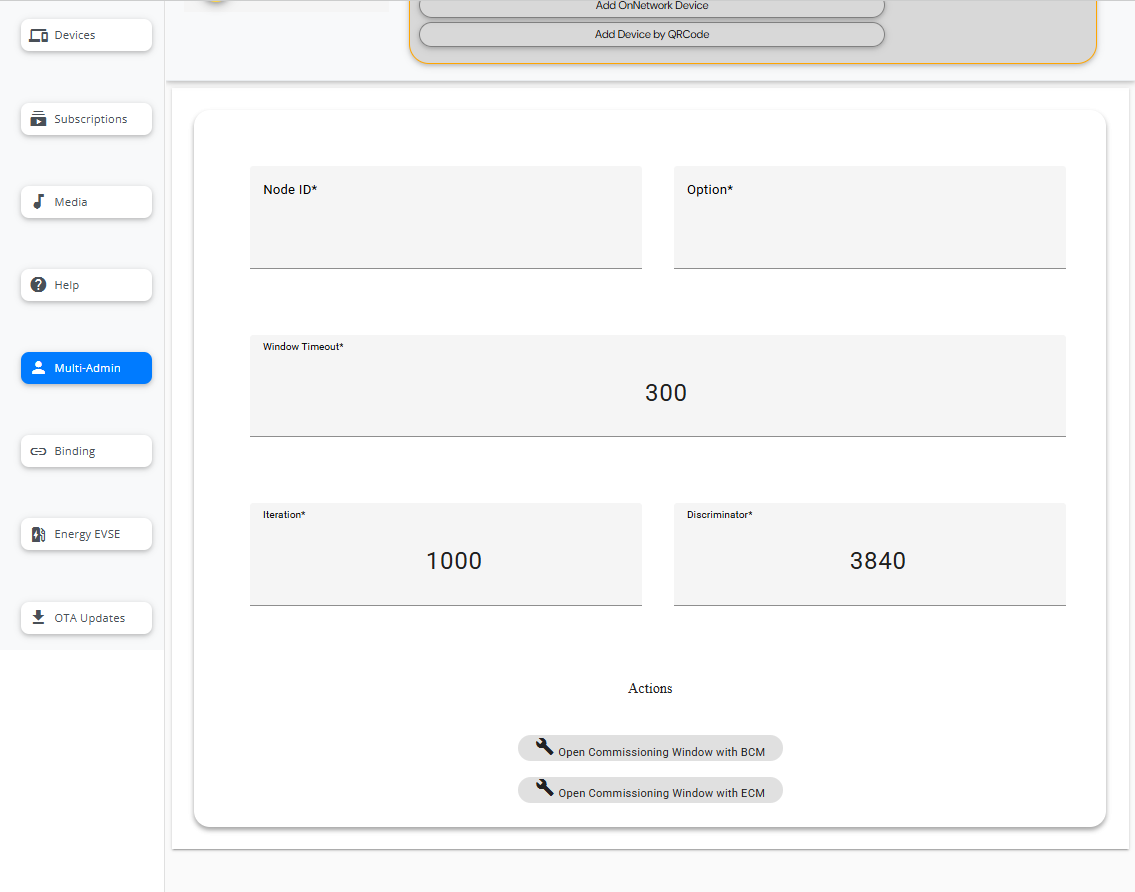
Enter Device ID, Commissioning Method, Window Timeout, Iteration and Discriminator. Then, click Open Window with BCM or Open Window with ECM button to trigger the Open Commissioning window:
$ chip-tool pairing open-commissioning-window <node_id> <option> <window_timeout> <iteration> <discriminator>
In this command:
<node_id> is the ID of the node that should open the commissioning window.
<option> is equal to
0for BCM and1for ECM.<window_timeout> is the time in seconds, before the commissioning window closes.
<iteration> is the number of PBKDF iterations to use to derive the PAKE verifier.
<discriminator> is device-specific discriminator determined during commissioning.
When using the ECM, a manual pairing code and QRCode like below in the web interface are shown. Then you can add this device on another administrator by Add Device by QRCode.
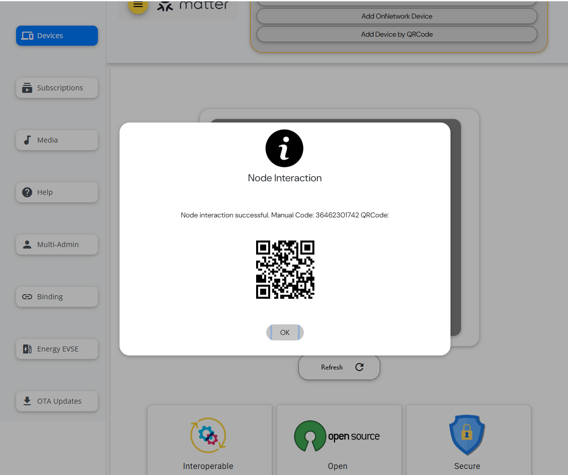
Besides, you can then commission the Matter device to a new fabric using another instance of the CHIP tool by the below command.
$ chip-tool pairing code <node_id> <payload>
In this command:
<node_id> is the user-defined device ID of the commissioned node.
<payload> is the QR code payload or a manual pairing code generated by the first commissioner instance when opened the commissioning window. If you used the BCM to open commissioning window, the manual pairing code should be
34970112332.
Controlling a Matter device Energy EVSE Cluster
Note: To perform EEVSE control-related operations on the chip-tool-web2, relevant parameters must be added. For example, run the application with the command “$chip-energy-management-app –enable-key 000102030405060708090a0b0c0d0e0f”, and then perform the on-network pairing operation on the chip-tool-web2.
Once the pairing process is complete, the Matter device is successfully commissioned to the network. For the chip-energy-management-app, the EEVSE clusters are implemented in chip-tool-web2, allowing you to control the end devices using the energyevse cluster commands.
To access the energyevse function in the chip-tool-web2, click the Energy EVSE button in the sidebar. The following interface is displayed:
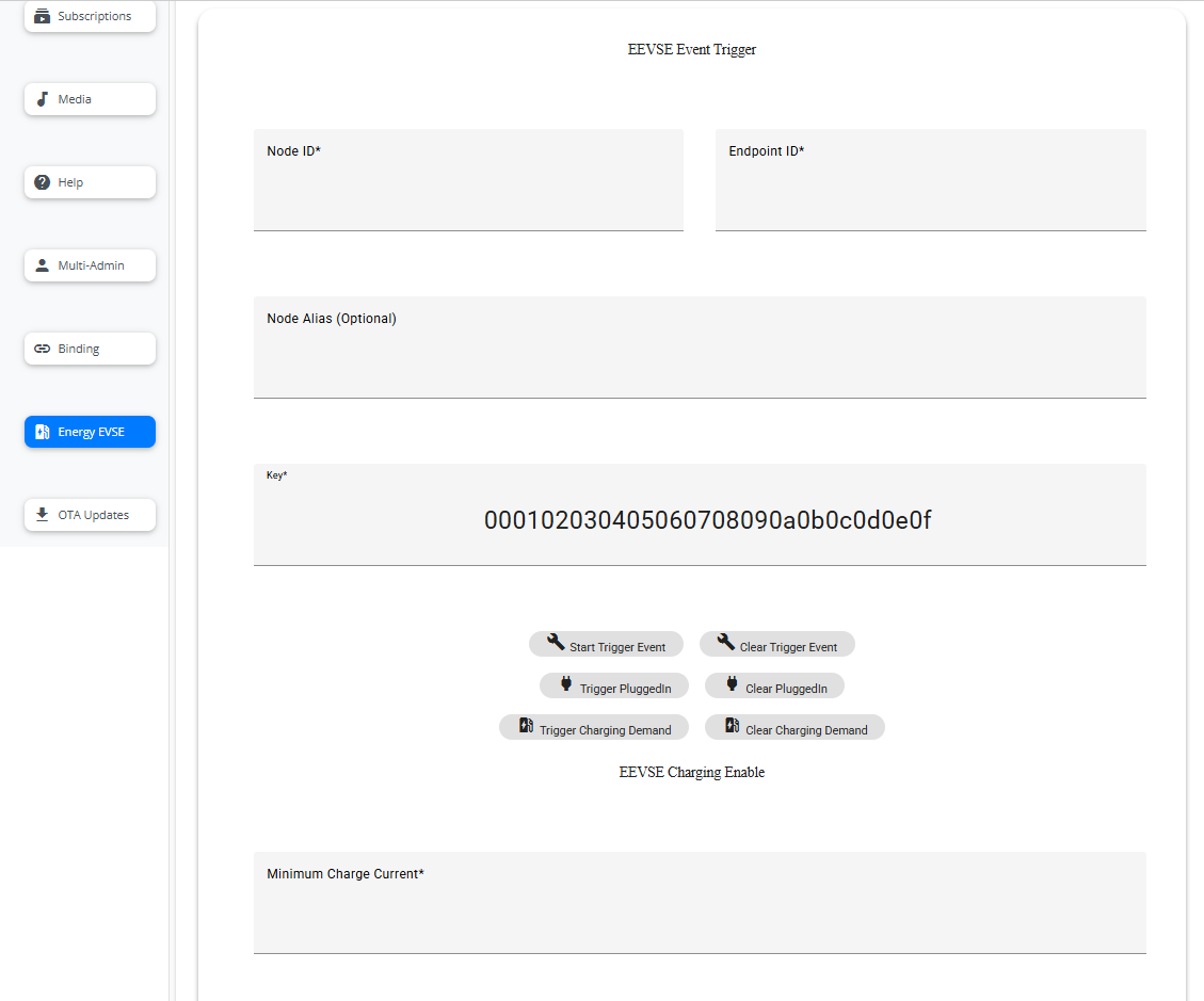
EEVSE Event Trigger
Enter the Device Alias, Device ID, and Endpoint ID of the commissioned Matter chip-energy-management-app device, then click the TRIGGERs or CLEARs button to trigger or clear the simulated event.
The
Start Trigger Eventbutton is used to simulate a start event as the basis for triggering subsequent simulated events.The
Trigger PluggedInbutton is used to simulate a plugged-in event. Indicates that electric vehicles are connected to the charging station. This event must be triggered after a start event has been triggered.The
Trigger Charging Demandbutton is used to simulate a charging demand event. Indicates that electric vehicles have a charging requirement. This event must be triggered after a plugged-in event has been triggered.The
Clear Trigger Eventbutton is used to clear the simulated start event.The
Clear PluggedInbutton is used to clear the simulated plugged-in event.The
Clear Charging Demandbutton is used to clear the simulated charging demand event.
When simulating events, the principle of “last trigger, first clear” should be used, for example, the order should be: Start Trigger Event – Trigger PluggedIn – Trigger Charging Demand – Clear Charging Demand – Clear PluggedIn – Clear Trigger Event
EEVSE Charging Enable
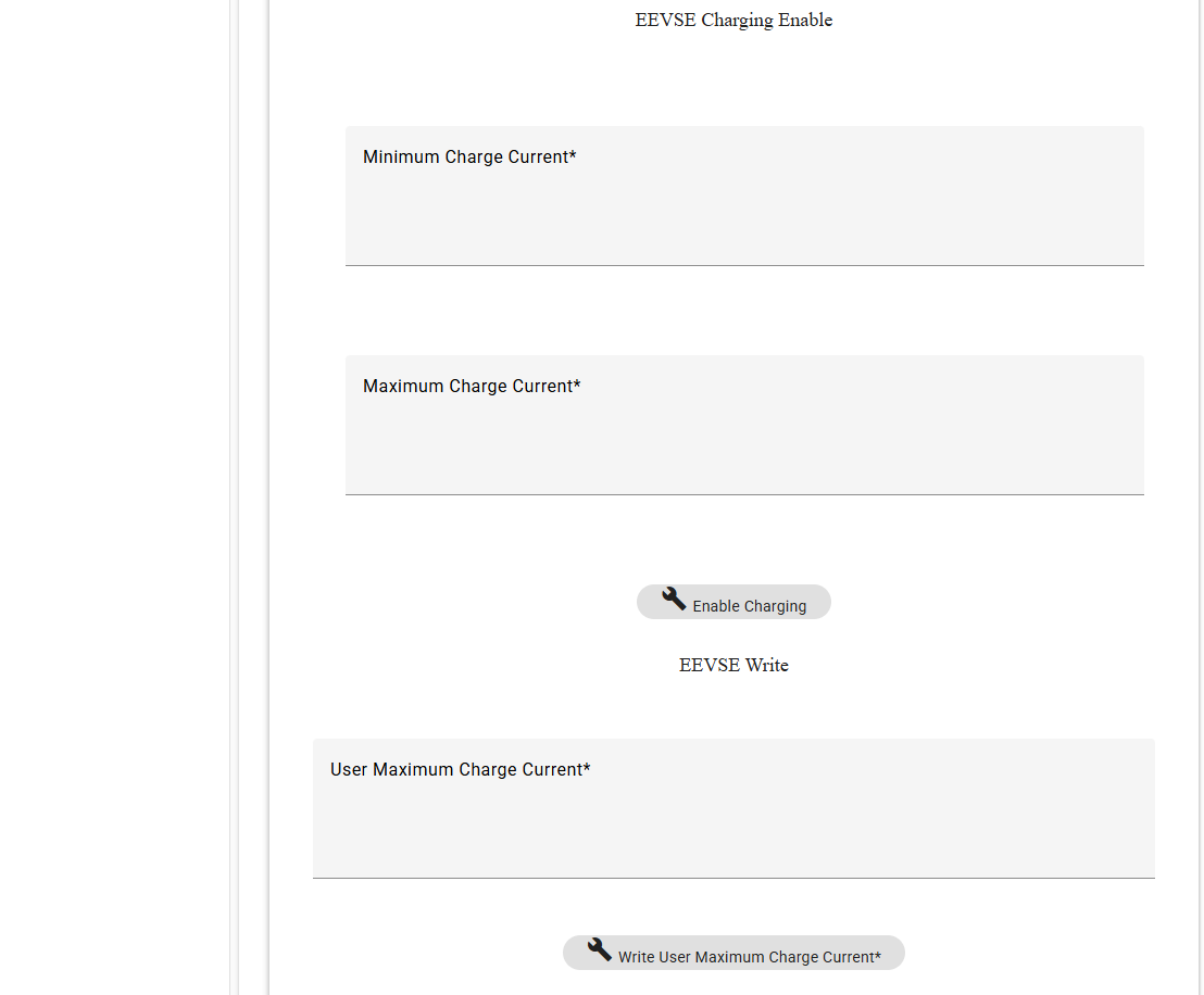
After the simulated charging demand event is triggered. Enter the value of Minimum Charge Current and Maximum Charge Current, and click the Enable Charging button to start charging by below commands.
$ chip-tool energyevse enable-charging null <minimum_charge_current> <maximum_charge_current> <node_id> <endpoint_id> --timedInteractionTimeoutMs 3000
In this command:
<minimum_charge_current> is the minimum charge current(mA).
<maximum_charge_current> is the maximum charge current(mA).
<node_id> is the user-defined ID of the commissioned node.
<endpoint_id> is the ID of the endpoint with energyevse cluster implemented.
EEVSE Write
Enter the value of User Maximum Charge Current and click the Write User Maximum Charge Current button to set user-maximum-charge-current attribute value by below commands.
chip-tool energyevse write <user_maximum_charge_current> <node_id> <endpoint_id>
In this command:
<user_maximum_charge_current> is the user-defined maximum charge current(mA).
EEVSE Charging Disable
Click the Disable Charging button to disable charging value by below commands.
chip-tool energyevse disable <node_id> <endpoint_id> --timedInteractionTimeoutMs 3000
EEVSE Status
Use the following buttons to read the status of the energyevse attribute in the EEVSE Status section. The page is shown below:
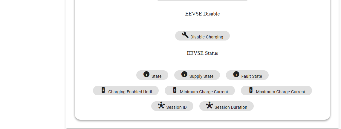
Use the
Statebutton to trigger the following command to read the state of energyevse:$ chip-tool energyevse read state <node_id> <endpoint_id>
Use the
Supply Statebutton to trigger the following command to read the supply-state of energyevse:$ chip-tool energyevse read supply-state <node_id> <endpoint_id>
Use the
Fault Statebutton to trigger the following command to read the fault-state of energyevse:$ chip-tool energyevse read fault-state <node_id> <endpoint_id>
Use the
Charging Enabled Untilbutton to trigger the following command to read the charging-enabled-until of tenergyevse:$ chip-tool energyevse read charging-enabled-until <node_id> <endpoint_id>
Use the
Minimum Charge Currentbutton to trigger the following command to read the minimum-charge-current of energyevse:$ chip-tool energyevse read minimum-charge-current <node_id> <endpoint_id>
Use the
Maximum Charge Currentbutton to trigger the following command to read the maximum-charge-current of energyevse:$ chip-tool energyevse read maximum-charge-current <node_id> <endpoint_id>
Use the
Session IDbutton to trigger the following command to read the session-id of energyevse:$ chip-tool energyevse read session-id <node_id> <endpoint_id>
Use the
Session Durationbutton to trigger the following command to read the session-duration of energyevse:$ chip-tool energyevse read session-duration <node_id> <endpoint_id>
Report Format
The EEVSE read report is output in text format with the following structure:
Report from ${nodealias} ${nodeid}:${endpoint}. Cluster:${cluster}
${attribute}:${value}
In the structure above,
${nodealias}: The node alias of the device.
${nodeid}: The nodeid of the device.
${endpoint}: The endpoint of the device.
${cluster}: The cluster name to which the device belongs.
${attribute}: The name of the attribute being reported. In this case, the default attributes are
state,supplystate,faultstate,chargingenableduntil,minimumchargecurrent,maximumchargecurrent,sessionid,sessionduration.${value}: The value of the attribute.
OTA updates on chip-tool-web2
The chip-tool-web2 supports uploading OTA file and controlling OTA processing. Click the OTA Updates in sidebar, the following page displays:
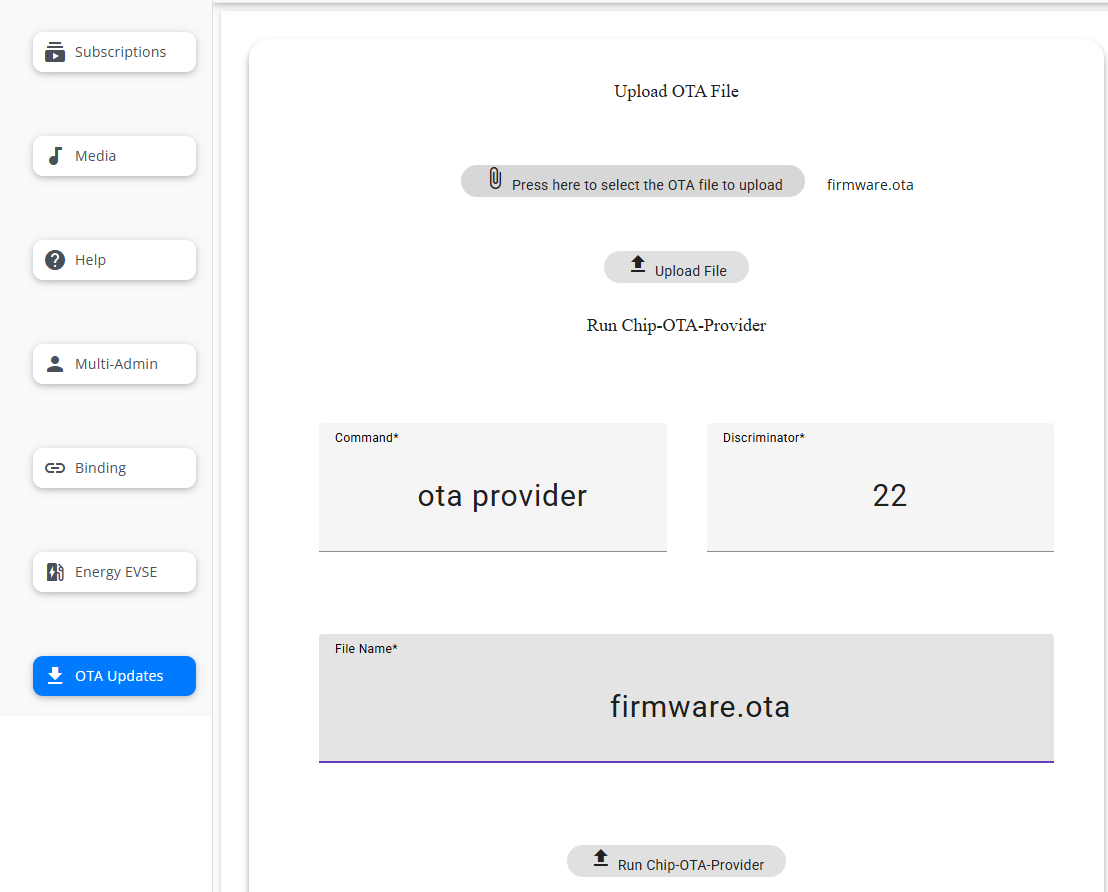
The OTA processing includes seven steps. Please follow the steps below strictly to perform the OTA process.
Step 1 Upload OTA file
Click the “Press here to select the OTA file to upload” button to select the OTA file from your browser’s running system. Then, click Upload File to upload the OTA file.
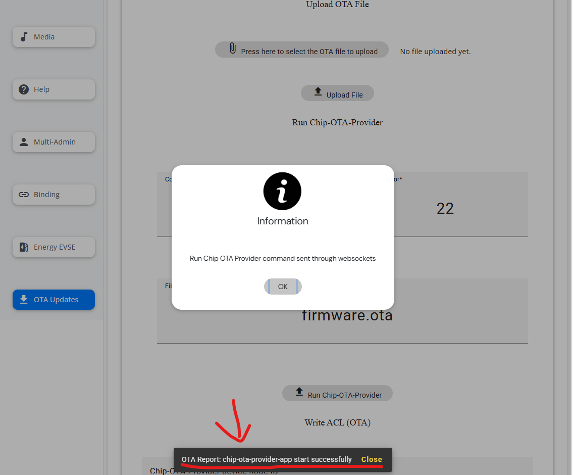
Step 2 Run chip-ota-provider-app
Enter the File name and click the chip-ota-provider-app button to run the chip-ota-provider-app on the chip-tool-web2 running i.MX controller device. Make sure the pop-up information “OTA Report: chip-ota-provider-app start successfully” shows that the chip-ota-provider-app started successfully.
Step 3 Commissioning with chip-ota-provider-app
Commissioning with chip-ota-provider-app in chip-tool-web2 by selecting Add OnNetwork Device.
Step 4 Run chip-ota-requestor-app in the end devices
Run the chip-ota-requestor-app on another device. Refer to chip-ota-request request processing.
Step 5 Commissioning with chip-ota-requestor-app
Commissioning with chip-ota-provider-app in chip-tool-web2 by selecting Add OnNetwork Device.
Step 6 Write ACL
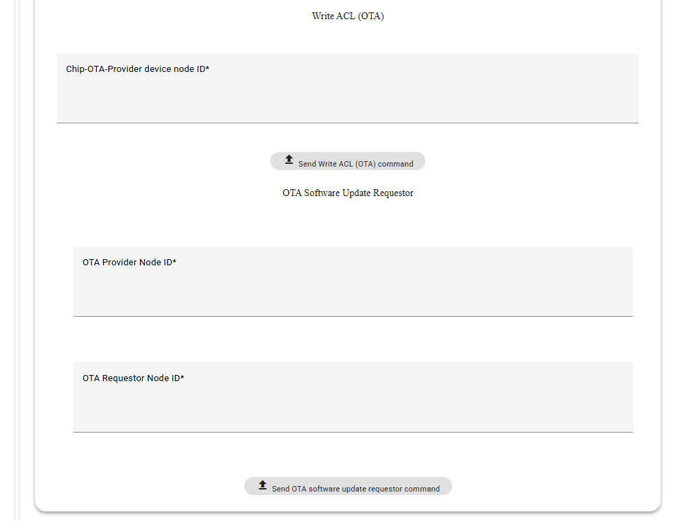
Enter the OTA Provider Device ID and click Send Write ACL (OTA) command in the Write ACL (OTA) section to start the write ACL processing.
Step 7 Send OTA command
Enter the OTA Provider Device ID and OTA Requestor Device ID, then click the Send OTA software update requestor command button to start the OTA processing. Notice the pop-up information “OTA Report: chip-ota-provider-app ota transfer successfully” to confirm that the OTA process has finished.
After completing the OTA process, check the OTA processing on the end device.
Network graph on chip-tool-web2
The chip-tool-web2 supports displaying the network topology of commissioned devices. Click the Network graph in sidebar, the following page is displayed:
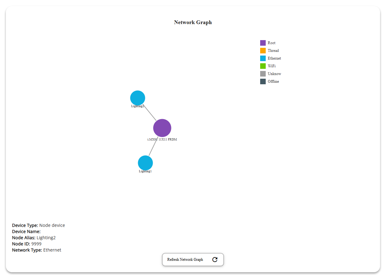
Clicking on a device node in the topology view will display detailed information in the bottom-left corner of the page:
Device Type: Displayed as either “Root device” or “Node device”.
Device Name: For root devices, this shows the name of the i.MX device.
Device Alias, Node ID, and Network Type: For node devices, these fields display the device alias, node ID, and the type of network the device is connected to.
Additional Notes
Deleting the
/tmp/chip_tool_config.inifile and any other.inifiles in the/tmpdirectory may help to resolve problems caused by outdated configuration. Runningrm -rf /tmp/chip_*removes these files. This allows the chip-tool-web2 to rebuild its configuration files from scratch.The timeout for buttons in the chip-tool-web2 that execute commands is set to the default timeout, for example, 125 seconds for pairing buttons and 20 seconds for cluster read buttons. During the command execution process, the interface displays the command execution waiting effect. Wait patiently for the command to finish executing and return a result of
successorfailed.In general, commands related to
Pairingmay take longer to execute, while commands related toOnOfffunctionality executes faster. If a pairing command takes a long time to execute and returns withfailed, check that the device configuration follows the documentation. Also, try pairing again after runningrm -rf /tmp/chip_*.The chip-tool-web2 supports commissioning multiple devices at the same time. You should not run
rm -rf /tmp/chip_*while commissioning multiple devices at once, as this will erase the useful information of the successfully paired devices.The chip-tool-web2 only supports commissioning devices with a decimal node ID, not a hexadecimal one.
New features are still being developed and expanded.